A high-quality HDPE geomembrane is the heart of a modern containment system, but the material itself is only half the story. The most common cause of failure we see in the field isn't a faulty product, but a flawed installation. A single bad weld can compromise the integrity of an entire project.
This comprehensive guide delivers a step-by-step procedure for HDPE geomembrane installation and welding, based on our experience supplying global projects. We will cover everything from initial site preparation and equipment selection to detailed welding techniques, rigorous quality control, and critical safety measures, ensuring your project achieves long-term, leak-free performance.
Before the first panel is unrolled, it's crucial to understand why this process demands such precision and to have the right tools ready for the job.
1. Introduction: The Role of HDPE Geomembranes in Containment Projects
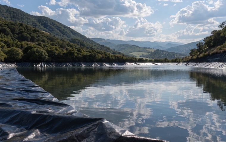
High-Density Polyethylene (HDPE) geomembranes are the material of choice for the world's most demanding containment applications, from landfill liners and mining heap leach pads to reservoir and canal linings. Their dominance stems from an exceptional combination of properties: superior chemical resistance, excellent durability against UV exposure, and an incredibly low permeability. These characteristics make HDPE the most reliable barrier for protecting the environment from contaminants.
However, these engineered properties are only realized when the individual panels are joined together to form a single, continuous, and impermeable sheet. This is achieved through thermal fusion welding. Unlike other materials that can be glued or taped, HDPE's non-polar molecular structure makes adhesive bonding impossible. The only way to create a permanent, leak-proof seam is to melt the surfaces together under controlled heat and pressure. This guide is dedicated to mastering that process.
2. Essential Tools and Equipment for HDPE Geomembrane Welding
Showing up to a job site without the proper equipment is the fastest way to guarantee project delays and poor-quality work. A professional installation crew carries a specialized arsenal of tools designed for welding, testing, and handling HDPE geomembranes.

Welding Equipment
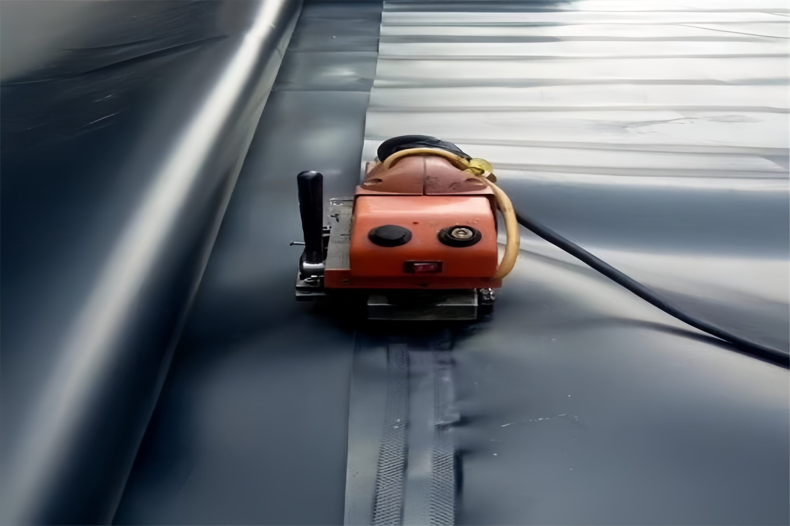
- Automatic Hot-Wedge Welder: This is the workhorse for long, straight seams. It uses a heated wedge to melt the overlapping surfaces of two geomembrane sheets while rollers apply constant pressure to fuse them. For thicker membranes (1.0 mm and above), larger models with steel rollers are used to provide adequate pressure. For thinner membranes (below 1.0 mm), smaller units with rubber rollers and lower power are preferred to avoid damaging the material.
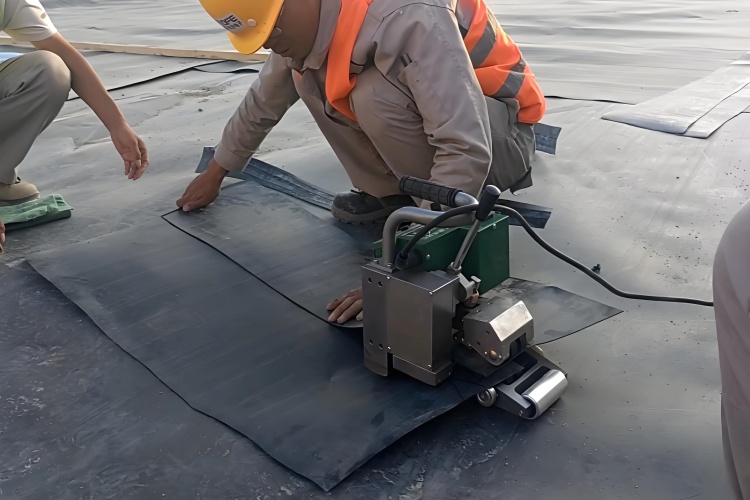
- Handheld Extrusion Welder: This tool is essential for detail work, repairs, and welding in tight spaces where the hot-wedge welder cannot operate. It works like a plastic-welding glue gun, heating a plastic welding rod and extruding a molten bead of HDPE onto the seam area to create a strong, continuous bond. It's used for patches, pipe boots, and corner details.
- Hot Air Gun: Used for temporary tack welding to hold panels in place before the main welding pass and for minor repair work.
Quality Control and Testing Equipment
- Vacuum Box: A clear box with a soft rubber gasket, used with a compressor to perform non-destructive testing on extrusion welds.
- Air Pressure Test Kit: Includes a pressure gauge and needle for testing the integrity of the air channel in double-track fusion welds.
- Tensiometer: A portable field device used to perform destructive peel and shear tests on trial weld strips, ensuring the welding parameters are correct.
General Tools
- Grinders for preparing surfaces before extrusion welding.
- Knives, shears, and measuring tapes.
- Sandbags for temporary anchoring.
- Cleaning supplies (rags and solvent if necessary, though water is often sufficient).
3. Preparation and Site Setup Before Welding
The success of a geomembrane installation is determined long before the first weld is made. Meticulous preparation is non-negotiable and provides the foundation for a durable, long-lasting liner system.
Subgrade Preparation
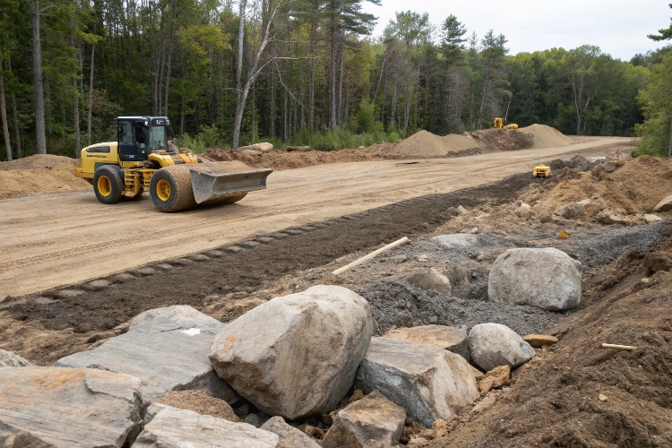
The subgrade is the soil or base layer upon which the geomembrane will be placed. It must be prepared to be a smooth, stable, and unyielding surface. The process involves:
- Surveying and Clearing: The area is surveyed to ensure it meets design elevations. All vegetation, large rocks, tree stumps, roots, and debris must be completely removed.
- Compactação: The soil is compacted to the density specified in the project plans. This prevents future settlement that could stress the liner.
- Surface Finishing: The final surface must be smooth and free of any sharp objects. Any projections or coarse gravel that cannot be removed must be covered with a cushioning layer, such as a minimum 15 cm (6-inch) layer of sand. A final roll-over with a smooth-drum compactor ensures a uniform surface.
Geotextile Underlayment
In many applications, especially over rocky or questionable subgrades, a protective non-woven geotextile is installed directly on top of the prepared subgrade. This adds a critical layer of puncture protection, acting as a cushion between the soil and the HDPE liner. A geotextile with a minimum weight of 300 g/m² is common for this purpose.
Panel Layout and Deployment
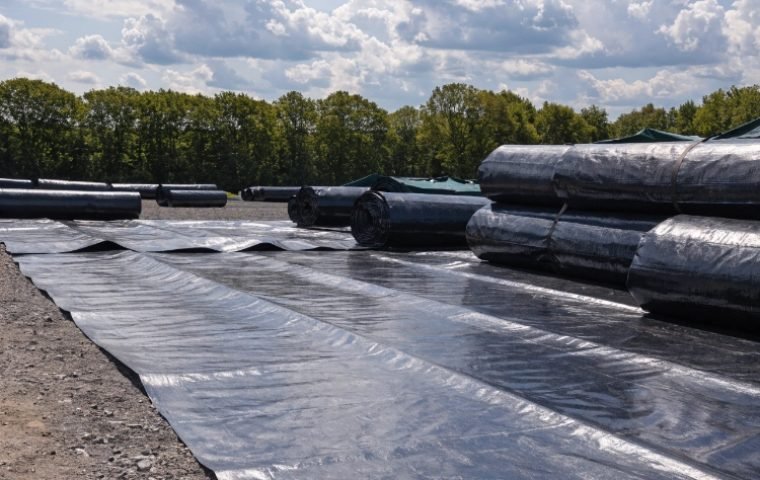
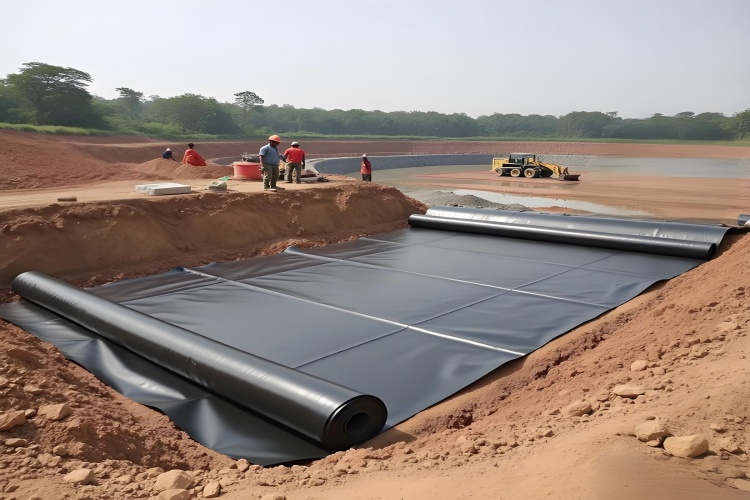
With the site prepared, the geomembrane panels are deployed according to an approved panel layout plan.
- Rolls should be deployed using a spreader bar on an excavator or other equipment to avoid dragging them on the ground.
- Work should preferably be done on calm days to prevent wind from getting under the sheets, which can be extremely dangerous.
- Panels should be positioned with a pre-determined overlap, typically 10-15 cm (4-6 inches), to allow for welding.
- It's important to allow some slack (3-5%) in the material to account for thermal expansion and contraction, but avoid excessive wrinkles, which can create problems during welding and backfilling.
4. Step-by-Step HDPE Geomembrane Welding Procedure
Welding is a technical skill that requires training, precision, and constant attention to detail. The process can be broken down into two main methods: fusion welding for long seams and extrusion welding for detail work.
Fusion Welding (Hot-Wedge Method)
This is used for the primary field seams connecting the main panels.
- Seam Preparation: Ensure the overlap area is clean, dry, and free of any dust, mud, or moisture. The required overlap width (usually 10-15 cm) must be consistent.
- Trial Weld: Before starting production welding each day, and any time conditions change, a trial weld must be performed on scrap pieces of the project's geomembrane. This test strip is then cut and tested with a field tensiometer to verify that the welder's temperature, speed, and pressure settings are correct.
- Welding: The hot-wedge welder is inserted into the overlap. As it travels automatically along the seam, the heated wedge melts the opposing surfaces, and the pressure rollers immediately fuse them together. A competent operator guides the machine to ensure it tracks straight and maintains a consistent pace. This process creates a double track weld with a small air channel in the middle, which can be tested for continuity.
Extrusion Welding
This manual method is used for repairs, patches, and welding around pipes, sumps, and corners.
- Preparação de superfície: The area to be welded must be lightly abraded with a grinder to remove the oxidized surface layer and create a rough texture for the molten plastic to bond to. The area must then be cleaned of all dust. For membranes thicker than 2mm, the edge of the patch should be beveled to a 45° angle to allow for a stronger weld.
- Tacking: The patch or boot is temporarily tacked into place using a hot air gun.
- Welding: The operator uses the extrusion welder to lay a continuous bead of molten HDPE over the prepared seam. The operator must move at a steady speed, applying consistent pressure with the welder's Teflon shoe to ensure a solid, void-free weld. The extrudate should flow out evenly on both sides of the bead, indicating good fusion.

5. Welding Parameter Guide: Thickness, Temperature, and Speed Reference
Achieving a perfect weld requires balancing three key variables: temperature, speed, and pressure. These parameters are not fixed; they depend on the geomembrane thickness and ambient weather conditions. The values below are a general starting point for trial welds, but final settings must always be confirmed by destructive testing.
| Membrane Thickness | Welder Type | Recommended Temperature Range (°C) | Recommended Speed Range (m/min) | Notas |
|---|---|---|---|---|
| 0.5 mm - 1.0 mm | Small Hot-Wedge | 280 - 360 | 1.5 - 2.5 | Requires lower pressure to avoid thinning the material. Very sensitive to overheating. |
| 1,5 mm | Standard Hot-Wedge | 300 - 400 | 1.0 - 1.8 | This is the most common range for many landfill and environmental projects. |
| 2.0 mm - 2.5 mm | Large Hot-Wedge | 350 - 450 | 0.8 - 1.5 | Requires higher pressure and temperature to ensure full fusion through the thicker material. |
| Extrusion Welding | Handheld Extruder | 220 - 280 (Extrudate) / 300 - 350 (Hot Air) | 0.2 - 0.5 | Speed is manually controlled. Focus on a consistent bead and even flow of extrudate. |
Important Note: Colder ambient temperatures require higher welding temperatures and/or slower speeds. Hotter ambient temperatures require lower welding temperatures and/or faster speeds. Always perform a trial weld to calibrate.
6. Quality Control and Field Testing Methods (ASTM Standards)
QC is not an afterthought; it is an integral part of the installation process. Every inch of weld must be proven to be leak-free. We use a combination of non-destructive and destructive testing methods based on internationally recognized ASTM standards.
Non-Destructive Testing (NDT)
NDT is performed on 100% of all field seams to ensure their continuity.
- Air Pressure Test (ASTM D5820): This test is used for double-track fusion welds. The air channel between the two welds is sealed at both ends, and a needle is inserted. The channel is pressurized to a specified level (e.g., 25-30 psi) and monitored for 5 minutes. A loss of pressure indicates a leak in the seam.
- Vacuum Box Test (ASTM D5641): This method is used for all extrusion welds. A soap solution is applied to the seam, and the vacuum box is placed over it, creating a seal with its rubber gasket. A vacuum is pulled. If bubbles appear in the soap solution, it indicates a leak.

Destructive Testing (DT)
Destructive tests are performed on the trial welds made at the start of each day and typically every 4-5 hours of production welding. A sample approximately 30 cm long and 2-3 cm wide is cut from the test seam and tested for both peel and shear strength using a field tensiometer (ASTM D6392). The weld must hold, and the failure must occur in the parent material (a "[Film Tear Bond" or FTB), not within the weld itself. This confirms the welding parameters are correct.
7. Identifying and Troubleshooting Common Welding Defects
Even experienced technicians can encounter issues. Knowing how to identify and correct them immediately is a sign of a professional crew.
Common Welding Flaws
- Cold Weld: The weld can be peeled apart by hand. It looks dull or has an uneven surface.
- Causa: Temperature is too low or speed is too high.
- Solução: Increase temperature and/or decrease speed. Re-weld the area after preparing the surface.
- Overheated Weld (Burnt Weld): The weld area is scorched, brittle, and may have smoke trails.
- Causa: Temperature is too high or speed is too slow.
- Solução: Decrease temperature and/or increase speed. The damaged section must be cut out and repaired with an extrusion-welded patch.
- "Fishmouth" or Wrinkle: A wrinkle in the sheet gets folded into the seam, creating a channel for leakage.
- Causa: Improper material layout or wrinkles in the sheet.
- Solução: Cut the fishmouth flat along the seam, and then cap the entire area with an extrusion-welded patch.
- Uneven Extrudate Flow: For extrusion welds, the bead of molten plastic is inconsistent or has gaps.
- Causa: Inconsistent travel speed, improper surface preparation, or an issue with the extruder.
- Solução: Grind off the bad weld, re-prepare the surface, and re-weld, focusing on consistent speed and pressure.
8. Safety Measures and Best Practices During Installation
A geomembrane installation site is a construction zone with unique hazards. Safety must be the top priority for every member of the crew.
- Personal Protective Equipment (PPE): All personnel must wear appropriate PPE, including hard hats, safety glasses, steel-toed boots, and gloves, especially when handling hot equipment.
- Electrical Safety: Welding equipment draws a lot of power. All generators, cables, and connections must be in good condition, properly grounded, and kept away from water.
- Handling Hot Equipment: Welders operate at extremely high temperatures (up to 450°C). They must be handled with care and placed on designated heat-resistant stands when not in use. Never leave a hot welder unattended on the geomembrane.
- Weather Conditions: Installation must halt during rain, high winds, or other adverse weather. Wind can lift panels, creating a serious safety risk and potentially damaging the liner. Welding in extreme temperatures (below 4°C or above 35°C) requires special procedures and frequent trial welds.
- Encostas: Working on slopes presents a slip-and-fall hazard. Ropes and safety harnesses may be required.
9. Final Verification and Key Takeaways for Long-Term Performance
The final steps of the installation lock in the quality of the work and provide the documentation needed for project sign-off.
- Final Inspection: A thorough visual inspection of the entire lined area is conducted. All welds are checked, and any identified defects are marked, repaired, and re-tested.
- Ancoragem: In anchor trenches, the geomembrane is laid into the trench, and the trench is carefully backfilled with compacted soil to provide a permanent mechanical termination for the liner system.
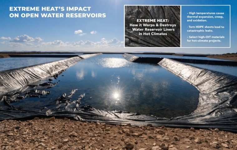
- Backfilling and Protection: As soon as practical after welding and QC are complete, the protective cover layer (soil, sand, or geotextile) should be placed. This protects the geomembrane from UV exposure, temperature swings, and mechanical damage.
- Documentação: Meticulous records are essential. The final documentation package should include as-built drawings showing a map of all panels and seams, a log of all destructive and non-destructive test results, and a record of all repairs.
Conclusão
A successful HDPE geomembrane installation is a testament to precision, expertise, and a systematic approach. It is not just about laying down plastic; it's about building a seamless, high-integrity containment system from the ground up. By following these steps—from meticulous site preparation to rigorous quality control—you ensure that the superior properties of the HDPE material are fully realized, providing robust, reliable, and long-lasting protection for your critical project.