يبدو خندق المرساة بسيطًا: احفر قناة، ثم ضع حافة البطانة، ثم ردمها. بالنسبة لبركة المزرعة، قد يكون ذلك كافيا. ولكن بالنسبة لمكب نفايات حديث ومصمم هندسيا، فإن هذه النظرة التبسيطية غير كافية بشكل خطير. لا يقتصر تثبيت البطانة على مكب النفايات فقط؛ إنه نظام هندسي بالغ الأهمية يدير الضغوط الهائلة، ويتحكم في هجرة الغاز، ويضمن سلامة الاحتواء لعقود من الزمن.
ك مورد المواد الاصطناعية الجيولوجية، لقد رأينا كيف أن حالات الفشل عند نقاط الإنهاء هي السبب الرئيسي لانتهاكات نظام الخطوط الملاحية المنتظمة المكلفة. وفي كاليفورنيا، أظهرت التحقيقات أنه حتى مدافن النفايات ذات البطانات السليمة يمكن أن تعاني من تلوث المياه الجوفية لمجرد أن غاز الميثان يتجاوز النظام عند حواف سيئة التصميم. ولهذا السبب فإن الفهم العميق للتثبيت والإنهاء الخاص بمكب النفايات أمر غير قابل للتفاوض. يوفر هذا الدليل المبادئ الهندسية التفصيلية المطلوبة لهذه البيئة عالية المخاطر.
لنبدأ باستكشاف العوامل الفريدة التي تميز مدافن النفايات.
1. معلمات التصميم الحرجة الفريدة لمدافن النفايات
تختلف القوى والظروف الموجودة في مكب النفايات اختلافًا جوهريًا عن أي تطبيق آخر للاحتواء.
- الإجهاد الميكانيكي الشديد: يمكن تكديس نفايات مدافن النفايات على ارتفاعات تتراوح بين 30 إلى 60 مترًا. يؤدي هذا الوزن الهائل (الذي يمارس ضغوطًا تزيد عن 600 كيلو باسكال) إلى خلق إجهاد شد وقص كبير على الغشاء الأرضي، خاصة على المنحدرات الجانبية. يجب أن يقاوم نظام المرساة قوى الجاذبية القوية والثابتة.
- ضغط الغاز والهجرة: يؤدي تحلل النفايات العضوية إلى توليد كميات كبيرة من غاز الميثان. يتراكم هذا الغاز تحت البطانة، مما يخلق ضغطًا صعوديًا ويبحث عن طرق للهروب. تعتبر نقاط انتهاء البطانة هي أكثر المسارات عرضة لانتقال هذا الغاز إلى التربة المحيطة والمياه الجوفية.
- أنظمة الخطوط الملاحية المنتظمة متعددة الطبقات: تستخدم مدافن النفايات الحديثة أنظمة مزدوجة البطانة للتكرار - بطانة أولية (على سبيل المثال، 2.0 مم HDPE) وبطانة ثانوية (على سبيل المثال، 1.5 مم HDPE أو GCL). يجب إنهاء هذه الطبقات بشكل مستقل لتعمل بشكل صحيح؛ ولا يمكن تجميعها ببساطة معًا في خندق واحد.
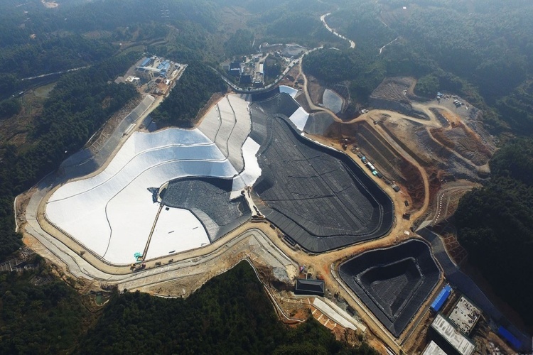
- البناء المرحلي في الخلايا: يتم بناء مدافن النفايات في خلايا منفصلة. وهذا يعني أنه يجب ربط أنظمة الخطوط الملاحية المنتظمة الجديدة بخبرة مع الأنظمة الموجودة عند السواتر بين الخلايا، مما يخلق تحديات معقدة في الإنهاء والاتصال تتطلب تخطيطًا وتنفيذًا دقيقًا.
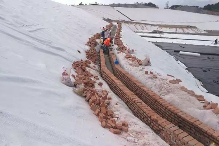
2. التصميم التأسيسي: خندق مرساة المكب
يعتبر خندق التثبيت هو أكثر طرق الإنهاء شيوعًا، ولكن بالنسبة لمكب النفايات، يجب أن يكون تصميمه دقيقًا ومدعومًا بالحسابات.
الأبعاد والشكل القياسي
| المعلمة | البعد النموذجي | ملحوظات |
|---|---|---|
| عمق | 0.75 م – 1.0 م | قد يكون من 1.0 إلى 1.5 متر للتطبيقات عالية الضغط. |
| عرض | 0.75 م – 1.0 م | يوفر كتلة ردم كافية للمقاومة. |
| انتكاسة من كريست | ≥ 0.6 م | يُبقي الخندق بعيدًا عن حافة المنحدر غير المستقرة. |
| زوايا | مدورة وليست حادة | يمنع تركيزات الضغط على مادة البطانة. |
عامل الاستقرار والسلامة
الغرض الأساسي من الخندق هو توفير قوة مقاومة كافية من تربة الردم لمواجهة قوى الشد على البطانة. يتم التحقق من ذلك باستخدام أ تحليل التوازن الحدي لحساب عامل السلامة (FOS).
FOS = Resisting Forces / Driving Forces ≥ 1.5
بالنسبة لمكب النفايات عالي الضغط، قد يكون FOS بمقدار 1.3 مقبولًا للبركة، ولكن بحد أدنى 1.5 ضروري. يجب أن يأخذ التصميم في الاعتبار القوى الناتجة عن الوزن الذاتي للبطانة، وتغطية التربة، وضغط المادة المرتشحة المحتملة، والانكماش الحراري. إذا أظهر التحليل FOS < 1.5 يجب زيادة عمق الخندق أو عرضه.
3. الإنهاء المتقدم للأنظمة متعددة الطبقات ومتعددة الخلايا
هذا هو المكان الذي يفصل فيه التصميم الخاص بمكب النفايات نفسه عن الممارسة العامة.
إنهاء أنظمة الخطوط المزدوجة بشكل منفصل
من الأخطاء الشائعة إنهاء الخطوط الأولية والثانوية في نفس الخندق. هذا غير صحيح. يجب إنهاء البطانة في خنادق منفصلة ومتوازنة أفقيًا.
لماذا؟ إذا تم قفل كلا البطانات في نفس كتلة الردم، فإن النظام يفقد استقلاله. يتم نقل الإجهاد أو التسوية أو الحركة الحرارية التي تؤثر على البطانة الأولية مباشرة إلى البطانة الثانوية، مما قد يسبب التجاعيد أو التوتر الذي يضر بسلامتها. يسمح فصل نقاط التثبيت لكل بطانة باستيعاب الضغط بشكل مستقل، مما يحافظ على التكرار الحرج للنظام.
ربط الخطوط في الحواجز بين الخلايا
عند بناء خلية جديدة مجاورة لخلية موجودة، يتم ربط البطانات عند الجدار الفاصل. ويتطلب ذلك اتصالاً قويًا حيث يتم نشر الغشاء الأرضي الجديد (الخلية 2). تداخل البطانة الموجودة والمثبتة من الخلية 1 بما لا يقل عن 0.6 إلى 1.0 متر. يتم بعد ذلك لحام هذا القسم المتداخل بشكل مستمر لإنشاء حاجز سلس وغير منفذ بين الخلايا.
4. النهايات الميكانيكية: التوصيل بالمنشآت الخرسانية
عندما يجب أن تنتهي البطانة مقابل هيكل خرساني مثل حوض المادة المرتشحة أو جدار الأساس، فإن خندق تثبيت التربة ليس خيارًا. هنا، مطلوب التثبيت الميكانيكي.
الطريقة القياسية هي استخدام شريط سمن.
- يتم ضغط الغشاء الأرضي بقوة على سطح خرساني نظيف وناعم.
- يتم وضع شريط مسطح من الفولاذ المقاوم للصدأ أو الألومنيوم (شريط القاعدة، على سبيل المثال، 30 × 50 مم) فوق الغشاء الأرضي.
- يتم دفع مسامير التثبيت عبر الشريط الخشبي والغشاء الأرضي إلى الخرسانة على فترات زمنية ضيقة، عادةً كل 0.3 إلى 0.4 متر.
- يتم تطبيق حبة متواصلة من مادة مانعة للتسرب متوافقة على طول الحافة العلوية لشريط الضرب لإنشاء ختم مانع لتسرب الماء.
بالنسبة للبناء الجديد، يمكن صب مقاطع HDPE المضمنة مباشرة في الخرسانة. يمكن بعد ذلك لحام الغشاء الأرضي مباشرة بشريط HDPE المدمج، مما يؤدي إلى إنشاء ختم متجانس ومتفوق.
5. إدارة المخاطر العالية: هجرة الغاز واختراق الأنابيب
هاتان اثنتان من نقاط الفشل الأكثر أهمية في نظام احتواء مدافن النفايات.
منع هجرة الغاز عند نقاط النهاية
الآلية الأساسية لتسرب الغاز هي الهجرة على طول حافة البطانة. ولمنع ذلك، يجب أن تكون جميع اللحامات عند نقاط النهاية تم اختباره بشكل مستمر وغير مدمر بنسبة 100%. يتم ذلك غالبًا باستخدام أ اختبار صندوق الفراغ، والذي يطبق الشفط على التماس للتحقق من وجود تسربات قد تكون غير مرئية للعين المجردة. وهذا يضمن أن المحيط بأكمله محكم الإغلاق.
الختم حول اختراق الأنابيب
اختراق الأنابيب هي نقاط تسرب سيئة السمعة. الطريقة الصحيحة تستخدم الجاهزة التمهيد الأنابيب HDPE. هذا مكون على شكل قمع ذو شفة مسطحة (تنورة) وياقة ضيقة (رقبة). التثبيت عبارة عن عملية لحام دقيقة من خطوتين:
- يتم لحام تنورة الحذاء المسطحة بالغشاء الأرضي الرئيسي باستخدام ماكينة لحام إسفينية ساخنة.
- يتم لصق طوق الحذاء حراريًا بالجدار الخارجي لأنبوب الاختراق باستخدام ماكينة لحام بالبثق، مما يخلق ختمًا متينًا ومستمرًا.
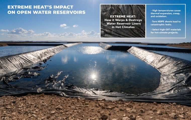
6. استيعاب القوى البدنية: الإجهاد الحراري وحساب الركود
HDPE has a high coefficient of thermal expansion, with surface temperatures on a landfill liner varying from -10°C in winter to over 70°C in direct summer sun. A liner installed too tightly will crack under tension in the cold. To prevent this, a calculated amount of "slack" يجب توفيرها.
يمكن حساب فترة الركود المطلوبة باستخدام الصيغة:
Slack = α × L × ΔT
أين:
αهو الخطي معامل التمدد الحراري لـ HDPE (~ 0.00015 / درجة مئوية).Lهو طول لوحة الخطوط الملاحية المنتظمة بين نقاط الربط.ΔTهو الحد الأقصى المتوقع للتغير في درجة الحرارة.
In practice, experienced installers often use a "thermal tensioning gauge" أو ضع البطانة مع تموج متحكم فيه أثناء التثبيت للتأكد من أن الارتخاء يقع ضمن النطاق المصمم - وهو ما يكفي لمنع التوتر، ولكن ليس لدرجة أنه يخلق تجاعيد كبيرة وإشكالية.
7. فرض التميز: ضمان جودة البناء (CQA) عند الإنهاء
بالنسبة لمدافن النفايات، يعد تقييم الجودة الشاملة عملية صارمة ومفوضة قانونًا. بالنسبة للتثبيت والإنهاء، فإن الأمر يتجاوز مجرد فحص بصري بسيط.
قائمة التحقق من CQA
يجب على موظفي CQA التحقق والتوثيق:
- أبعاد خندق المرساة: يتم إجراء فحوصات منتظمة (على سبيل المثال، كل 60 مترًا) للتأكد من أن عمق الخندق وعرضه وارتفاعه ضمن حدود تسامح التصميم (على سبيل المثال، ±10%).
- بطانة الركود: تأكيد مرئي بأنه قد تم ترك ارتخاء كافٍ في البطانة قبل ردم الخندق.
- ضغط الردم: التحقق من وضع الردم في مصاعد رفيعة (<15 سم) ومضغوطة حسب المواصفات (على سبيل المثال، ≥95% MDD)، ولا تعمل هذه المعدات مطلقًا بشكل مباشر على البطانة.
- سلامة اللحام: فحص بنسبة 100% واختبار غير مدمر لجميع اللحامات عند النهايات الميكانيكية والاختراقات.
علاج الخلل
يجب أن تتضمن خطة CQA أيضًا بروتوكولات لإصلاح العيوب الشائعة.
| عيب | السبب المشترك | علاج | معايير قبول CQA |
|---|---|---|---|
| البرك | قاع الخندق غير المستوي | أعد تصنيف قاع الخندق وأعد التحقق | الارتفاع ضمن ±5 سم |
| التجاعيد | الركود المفرط | ضبط الخطوط الملاحية المنتظمة لتقليل ارتفاع الموجة | التجاعيد < ارتفاع 5 سم |
| التوتر التماس | ركود غير كاف | قطع وتصحيح التماس للافراج عن التوتر | تتوافق الرقعة مع قوة التماس بنسبة 100% |
خاتمة
يعد تثبيت وإنهاء الغشاء الأرضي لمكب النفايات بشكل صحيح نظامًا معقدًا يتطلب مستوى أعلى من الهندسة والتنفيذ. فهو يتطلب تصميمًا شاملاً يدمج المعرفة بميكانيكا التربة وعلوم المواد وأفضل ممارسات البناء. بدءًا من حساب عمق الخندق الصحيح ومساحة الركود وحتى تنفيذ عمليات لحام خالية من العيوب على أحذية الأنابيب، فإن كل التفاصيل مهمة. ومن خلال التعامل مع نقاط النهاية هذه بالاهتمام الدقيق الذي تستحقه، فإنك تضمن سلامة نظام الاحتواء بأكمله.