When a mine ceases production, the revenue stops, but the liability begins. The closure of a mine does not signal the end of environmental responsibility; in fact, it often marks the beginning of the most critical phase in a Tailings Storage Facility’s (TSF) lifecycle.
While the processing plant is dismantled and the fleet is sold, the tailings remain. These millions of tons of crushed rock and chemical residue are chemically and structurally active. They do not simply "sit" there. Without active management, they react with oxygen and water, generating acid, mobilizing heavy metals, and exerting immense pore pressure on containment structures.
This guide examines the engineering controls required for safe mine closure, focusing on how composite geosynthetic barrier and drainage systems mitigate the long-term risks of seepage, instability, and environmental contamination.
Safe containment after mine closure depends on engineered barrier systems, drainage control, and long-term monitoring. It is not about burying the waste; it is about isolating it from the hydrological cycle.
What Engineering Risks Must Be Controlled After Closure?
The fundamental challenge of mine closure is that TSFs are predominantly constructed from earth and rock, yet they are expected to contain fluid and semi-fluid waste for centuries. Unlike a concrete structure with a defined design life, a TSF must perform in perpetuity.
From my experience supplying materials to TSF projects in South America and Southeast Asia, I have seen that the failure to anticipate post-closure risks during the design phase is the primary cause of expensive remediation later.
There are four specific engineering risks that must be controlled:
1. Seepage and Groundwater Contamination
This is the silent killer of mining budgets. Even if a dam is structurally stable, seepage can transport dissolved heavy metals (arsenic, weak acid dissociable cyanide, lead) into the local aquifer.
- The Mechanism: As the hydraulic head within the tailings mass settles, gradients force pore water downward. Without an impermeable barrier, this water migrates into the subgrade.
2. Acid Mine Drainage (AMD)
When sulfide-bearing minerals in tailings (like pyrite) are exposed to air and water, they oxidize to produce sulfuric acid. This acid then dissolves other heavy metals, creating a toxic leachate.
- The Control: The goal of closure is to prevent oxygen and water ingress. If you can stop the water from entering the top and stop the leachate from escaping the bottom, you starve the reaction.
3. Structural Instability of Tailings Mass
Tailings are loose, unconsolidated silts. If they remain saturated, they are susceptible to liquefaction during seismic events (earthquakes). A TSF that appears stable while operating can fail decades later if drainage systems clog and pore pressure rises.
- A correção: Effective drainage is not just for water quality; it is for physical stability. Drying the tailings stack is the only way to increase shear strength.
4. Long-Term Regulatory Liability
In jurisdictions like Australia, Canada, and Chile, mining companies must post financial assurance bonds. These bonds are only released when the site is deemed chemically and physically stable. "Walk-away" solutions do not exist anymore. If the site leaks, the bond is forfeited, and reputation is destroyed.
Water infiltration is the primary driver of post-closure failure. Uncontrolled seepage increases long-term remediation costs by orders of magnitude compared to the initial cost of installing a proper liner system.
The Role of Engineered Containment Systems
In modern mining engineering, we no longer rely on clay alone to hold back chemical waste. The standard for safety has shifted to Composite Geosynthetic Containment Systems.
Safe containment is achieved through layered defense systems rather than single-material solutions. A single layer of HDPE is a barrier; a system of HDPE, GCL, and drainage composites is a solution.
Primary Barrier Systems
The base of the TSF is the most critical component because it cannot be repaired after deposition begins.
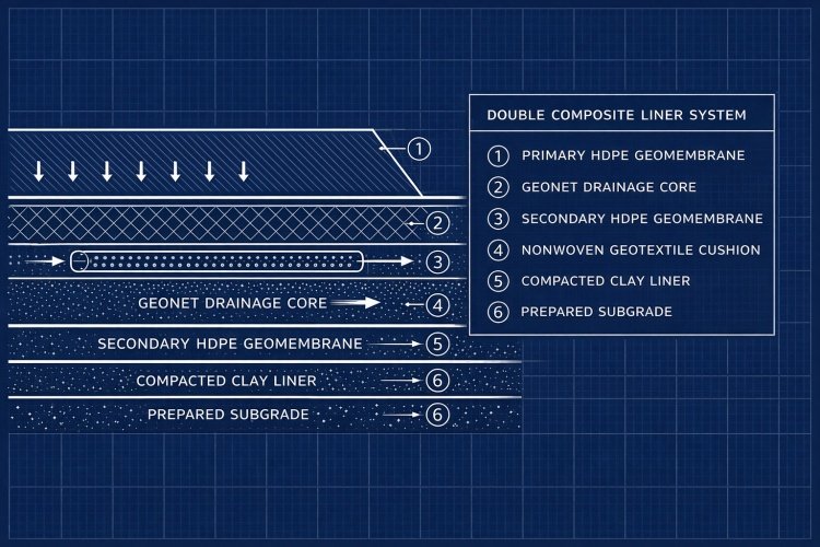
- The Standard: A composite liner consisting of a Geomembrane (usually 1.5mm or 2.0mm HDPE) placed directly over a low-permeability soil layer or a Geosynthetic Clay Liner (GCL).
- The Logic: If the geomembrane develops a pinhole defect (which can happen during installation), the GCL below it swells upon contact with the liquid, sealing the leak. This composite action reduces leakage rates by virtually 99% compared to a geomembrane alone.
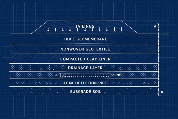
Continuous Drainage Control
You cannot just trap water inside the TSF; you must manage it.
- Underdrains: Placed below the liner to prevent groundwater from pushing up (whales) against the liner.
- Overdrains (Leachate Collection): Placed above the liner to collect drainage from the tailings mass. By removing this water, you reduce the hydraulic head on the liner, further reducing leakage risk.
Redundancy and Leak Detection
For high-risk facilities (like cyanide heap leach pads or uranium tailings), we often supply Double Composite Liner Systems.
This involves two distinct liner systems separated by a leak detection drainage layer. Even if the primary liner is breached, the secondary liner captures the fluid, and the drainage layer signals the leak to the operators immediately.
Closure Capping Systems and Water Infiltration Control
Most people focus on the bottom liner, but in the post-closure phase, the Final Cover System (Capping) is equally important.
If you seal the bottom but leave the top open, you create a "bathtub effect." Rainwater fills the TSF, causing it to overflow or increasing pressure until the dam bursts. Controlling rainfall infiltration is critical for reducing acid generation and seepage risk.
Surface Water Management
The first line of defense is geometry. The closed TSF must be contoured to shed surface water away from the tailings mass without causing erosion. This usually involves engineered slopes and armored drainage channels.
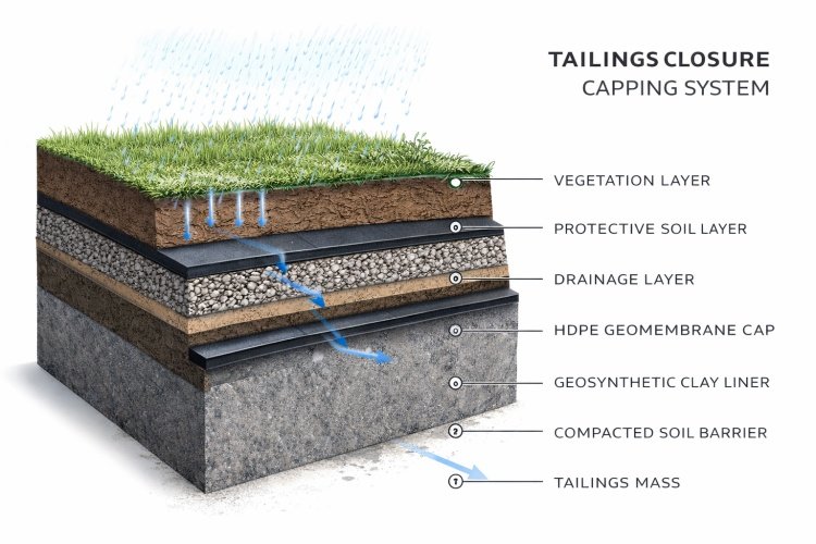
The Composite Cap Design
Just like the bottom liner, the top cap often utilizes geosynthetics:
- Foundation Layer: A grading layer over the settled tailings.
- Barrier Layer: A Linear Low-Density Polyethylene (LLDPE) geomembrane or Co-extruded Geomembrane/GCL composite. We use LLDPE here because it is more flexible than HDPE and can accommodate the differential settlement of the tailings as they dry out over years.
- Drainage Layer: A drainage geocomposite placed above the barrier to interrupt infiltrating water and drain it to the perimeter.
- Vegetative Soil Layer: Topsoil to support native vegetation, stabilizing the surface against wind and water erosion.
The cap serves two purposes:
- Infiltration barrier: It keeps the tailings dry ("Dry tomb" approach).
- Oxygen barrier: It minimizes the oxidation of sulfide minerals, slowing down acid generation.
Modern Trends: Dry Stack Tailings and Enhanced Stability
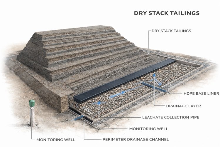
The industry is moving away from large, wet tailings dams toward Dry Stack Tailings (DST). This method involves filtering moisture out of the tailings before deposition, creating a soil-like material that can be compacted.
Why this matters for closure:
- Reduced Liquefaction Risk: Dry stacks do not rely on a dam wall to hold back fluid. They are geotechnically stable piles.
- Smaller Footprint: They can be stacked higher and steeper, reducing the land area that needs to be lined and capped.
However, "Dry" does not mean "Waterproof".
Even dry stack facilities rely on properly designed base liner and drainage systems. Rainwater falling on a dry stack will still leach contaminants. As an exporter, we see a growing demand for high-friction textured geomembranes specifically for the base of dry stack facilities, where slope stability is critical.
Selecting the Right Geosynthetic Materials for Long-Term Performance
Safety in mine closure is theoretical until it is translated into physical materials. The selection of the specific geosynthetic grade dictates the longevity of the containment.
Here is how we guide mining clients on material selection for closure applications:
HDPE Geomembrane – Primary Containment Barrier
For base liners, Polietileno de alta densidade (HDPE) is the non-negotiable standard.
- Por que: It offers the highest chemical resistance of any geosynthetic. It is impervious to the UV radiation (if exposed) and the aggressive acids found in leachate.
- Specification: For TSFs, we recommend a minimum thickness of 2.0mm (80 mil). The extra thickness provides a safety factor against stress cracking and puncture during the loading of thousands of tons of ore.
Forro de argila geossintética (GCL) – Secondary Containment
GCLs are replacing compacted clay liners in many regions because they save volume.
- Por que: A 6mm thick GCL provides the same hydraulic barrier as 300mm–500mm of compacted clay.
- Role: It acts as the self-sealing "insurance policy" under the geomembrane.
Geotextiles – Protection and Filtration
Non-woven geotextiles serve two distinct roles in closure:
- Cushion: Heavy-weight geotextiles (800g/m²+) protect the liner from puncture by the subgrade stones.
- Filtragem: They wrap drainage pipes and geocomposites, preventing fine tailings particles from clogging the flow paths. If the filter clogs, the drainage stops, and the dam becomes unstable.
Drainage Geocomposites – Leachate Management
These are tri-planar or bi-planar nets bonded to geotextiles.
- Por que: They replace traditional gravel drainage layers. Hauling gravel to a remote mine site is expensive. A single roll of geocomposite can replace tons of aggregate.
- Performance: They maintain high transmissivity (flow rate) even under high compressive loads, ensuring the TSF remains drained.
Risk, Limitations, and When Geosynthetics Are NOT Enough
While geosynthetic systems are the industry standard for containment, they are not magic solutions. There are specific scenarios where relying solely on a liner is unsafe or where engineering controls must go beyond material selection.
1. The Limit of Slope Stability (Interface Friction)
A common failure mode in closed TSFs is a veneer failure of the cover system. This happens when the soil placed on top of the geomembrane cap slides off during heavy rain.
- The Risk: The interface between a smooth geomembrane and soil has very low friction.
- The Constraint: You cannot just "cover it and leave it." You must use Textured Geomembranes with aggressive asperities to lock into the soil and potentially geogrids to anchor the soil layer.
2. Temperature Limitations
In some sulfide-rich mines, the oxidation process is exothermic—it generates heat. Tailings can reach temperatures of 60°C to 80°C.
- The Risk: Standard HDPE loses strength and degrades faster at sustained high temperatures.
- The Limitation: If high temperatures are predicted, standard HDPE is not suitable. You must specify High-Temperature formulations or specialized antioxidants (High-Pressure OIT testing) to ensure the liner survives the closure period.
3. Seismic Catastrophes
A liner only contains the fluid; it does not hold up the dam wall.
- The Reality: If the embankment dam itself is structurally unsound due to poor geotechnical engineering (e.g., upstream construction method on a fault line), the liner will simply rip apart when the dam collapses. Geosynthetics cannot fix bad geotechnical engineering.
Conclusion: Safe Containment Requires Engineered Systems
Mine closure does not remove risk; it simply shifts the focus from production operational efficiency to long-term chemical and physical stability.
The history of tailings dam failures teaches us that relying on natural geology or simple earthworks is insufficient. Safe containment depends on engineered multi-layer systems:
- Composite Liners to prevent seepage.
- Drainage Systems to maintain physical stability.
- Capping Systems to isolate the waste from the environment.
Properly designed geosynthetic containment systems play a critical role in ensuring long-term environmental protection and regulatory compliance.
If you are evaluating closure strategies or selecting materials for a TSF expansion, ensure your choices reflect the long-term reality of the site, not just the short-term budget.