In the forensic engineering of heap leach failures, there is a recurring pattern that most operators miss until it is too late. When a leak is detected in a heap leach pad—whether it is a copper project in the Andes or a gold mine in Central Asia—the immediate reaction is to blame the containment barrier.
The investigation usually starts with the geomembrane: Was the welding done correctly? Was the resin quality sufficient? Did the installer leave a scratch? However, after participating in numerous site evaluations and post-failure analyses, I can tell you that the geomembrane material itself is rarely the root cause.
The plastic did not fail because it was "bad plastic." It failed because the environment it was forced to operate in changed drastically from the design assumptions.
This guide explains the invisible mechanism of liner failure—moving beyond simple installation defects to understand how poor drainage triggers a hydro-mechanical chain reaction. We analyze how solution accumulation creates hydraulic currents that destroy containment systems from the inside out.
In the majority of operational liner failures, the culprit is hydraulic, not structural. The failure sequence begins with a compromised drainage layer, leads to solution accumulation within the heap, and ends with the physical rupture of the liner due to elevated hydraulic head.
We will move beyond the simple concept of "leakage" to understand the physics that destroy large-scale containment systems.
For a foundational understanding of how to engineer these layers correctly to prevent the issues discussed below, I recommend reading our companion guide: Por que o projeto da camada de drenagem é fundamental para o desempenho da camada de lixiviação?
2. What Engineers Mean by “Solution Accumulation” (and Why It’s Often Invisible)
When we talk to site operators about "solution accumulation," many visualize a dramatic, visible event: a lake forming on top of the ore stack or solution flooding over the perimeter berms.
While surface ponding is a symptom of permeability issues in the top layer of the ore (often due to decrepitation or compaction), it is not the type of accumulation that kills liners. The accumulation that leads to catastrophic liner failure happens at the bottom, deep beneath the ore stack, at the microscopic interface between the liner and the drainage layer. This is the "hidden killer" because it occurs under 100 meters of rock, completely out of sight.
2.1 Solution Accumulation Is Not Always “Ponding”
To understand the risk, we must distinguish between three distinct hydraulic states within the pad:
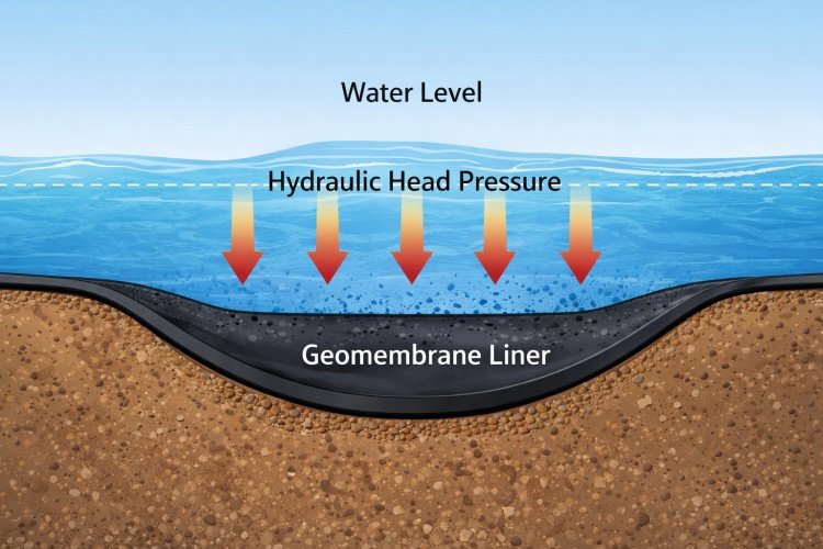
- Free Drainage (The Design State): In an ideal scenario, the Pregnant Leach Solution (PLS) percolates through the ore and flows freely through the drainage layer (gravel or geonet) into the collection pipes. The "phreatic surface" (the water level) is virtually non-existent, perhaps only a few millimeters high inside the drainage media. The hydraulic head on the liner is negligible (typically <300mm). In this state, the liner acts as a flow surface, not a pressure vessel.
- Inter-Drain Mounding (The Hidden Risk): This is the most common precursor to failure. Here, the drainage layer cannot evacuate fluid as fast as it arrives—perhaps due to partial clogging or insufficient transmissivity under load. The fluid level rises between the collection pipes. While the pipes are flowing full, the area between them is saturated. This creates "mounds" of hydraulic pressure acting on the liner. The operator sees flow at the outlet, but the liner is experiencing 1 to 3 meters of head pressure between the pipes.
- Submerged System (The Failure State): The drainage capacity is completely overwhelmed. The entire piping network is underwater. The bottom meters of the heap are saturated. The liner is now subjecting to hydrostatic pressure across its entire surface area. This effectively turns the heap leach pad into a dam, a function the liner was never structurally designed to perform.
2.2 Why Operators Often Miss Early Accumulation
The most dangerous aspect of solution accumulation is that it is often undetectable via standard flow meters until the damage is done.
An operator might look at the PLS pond and see a steady flow coming from the discharge pipes. They assume, "The pipes are flowing, so the pad is draining."
This is a fatal assumption.
Flow rate measures volume out, not pressure in. A drainage pipe can be flowing at 100% capacity while the head pressure behind it continues to rise. It is analogous to a bathtub with a partially clogged drain: water is still flowing out, but the tub is filling up because the input exceeds the output. By the time you realize the drainage layer is overwhelmed—perhaps because you see seepage at the toe of the slope—the hydraulic head at the bottom of a 100-meter stack may have already exceeded critical design limits.
3. The Failure Chain: How Poor Drainage Gradually Destroys a Liner System
Liner failure due to poor drainage is rarely an instantaneous event. It is a progressive deterioration process that follows a specific chain of causality. Understanding this timeline is the only way to interrupt it.
3.1 Stage 1 – Drainage Efficiency Degradation Over Time
The process starts with the degradation of the drainage layer’s transmissivity (flow capacity). In my experience, this usually involves one or more of the following mechanisms, often occurring 3 to 5 years into the mine's life plan:
- Creep and Crushing: Under high overburden loads (especially in heaps >80m), traditional gravel drainage layers can degrade. The stones crush against each other at contact points, breaking down and creating "fines" that clog the interstitial voids. Similarly, under-specified geonets can suffer from compressive creep, where the plastic ribs flatten or "roll over," closing the flow channels.
- Pipe Ovalization: Collection pipes are subjected to immense vertical pressure. If the pipe wall thickness (SDR) is insufficient, or if the gravel bedding angle is poor, the pipes can ovalize. A 10% deflection in pipe shape can result in a significant loss of flow velocity, promoting sediment settlement inside the pipe.
- Chemical Scaling: Leaching chemistry is aggressive. Even if the ore is clean, chemical reactions occur. Gypsum (calcium sulfate), calcite, or jarosite precipitates can crystallize within the drainage media or geotextiles, cementing the layer and reducing permeability by orders of magnitude.
- Fines Migration: As the ore decrepitates (breaks down) under acid attack, clay fines migrate downward. If the protective geotextile filter or the gravel filter criteria are not perfectly matched, these fines enter the drainage layer and block it.
At this stage, the liner is still perfectly intact, but the capacity of the system to remove liquid is fading.
3.2 Stage 2 – Hydraulic Head Build-Up at the Liner Interface
As drainage efficiency drops, the system can no longer handle the infiltration rate from irrigation and rainfall events. The PLS has nowhere to go but up.
Fluid begins to accumulate in the pore space of the drainage layer and effectively saturates the bottom lift of the ore. In "Valley Fill" heap leach pads, this mechanism is particularly aggressive because the V-shape geometry funnels all fluid to a central axis. If the central drain is compromised, the hydraulic head rises rapidly, transforming the bottom of the valley into a pressurized reservoir.
We have documented cases where the hydraulic head (fluid depth) on the liner rose from the design limit of 0.3 meters to over 15 meters.
3.3 Stage 3 – Stress Redistribution on the Liner
This is the phase where physics turns against the plastic. A geomembrane liner is designed to function primarily as an impermeable barrier, held in place by friction and the weight of the ore.
When hydraulic head builds up, three mechanical changes occur:
- Uplift Pressure: The fluid pressure pushes against the liner. If there is even a pinhole leak, fluid enters the interface between the liner and the subgrade. This can create a "waterbed effect," lifting the liner slightly and detaching it from the subgrade friction that holds it in place.
- Effective Stress Reduction: High pore pressure reduces the effective stress of the soil/ore mass. This can lead to localized shifting or settlement of the subgrade.
- Shear Stress Activation: As the saturated bottom layer of ore becomes unstable (slurry-like), it may mobilize slightly down-slope. The liner, sandwiched between a shifting heavy mass and a rough subgrade, is subjected to massive shear forces it was not designed to withstand.
3.4 Stage 4 – Liner Damage Initiation
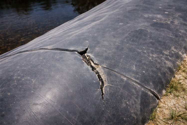
Under these abusive conditions, the "perfect" liner begins to fail. The dominant mechanism here is usually Environmental Stress Cracking (ESC).
- Stress Cracking: Polietileno de alta densidade (HDPE) is a semi-crystalline polymer. It is excellent at chemical resistance but susceptible to cracking under long-term localized stress. If a sharp piece of gravel is pressing into the liner (create a point load), and the liner is under global tension due to the hydraulic head or shear forces, the polymer chains will slowly unravel (disentangle). This creates a brittle crack, not a ductile tear.
- Defect Propagation: A microscopic scratch or an imperfect extrusion weld that would have remain harmless under low-head conditions now becomes a stress concentration point. The elevated pressure acts as a wedge, driving the failure mechanism and propagating small defects into open splits.
3.5 Stage 5 – Leakage Escalation and Environmental Impact
Once a breach occurs—even a small crack—the elevated hydraulic head acts as a massive force multiplier.
According to Bernoulli’s principle e Darcy’s law, the flow rate of leakage through a defect is proportional to the square root of the hydraulic head.
- No 0.3m of head (good drainage), a 10mm hole might leak a manageable drip.
- No 15m of head (bad drainage), that same hole becomes a high-pressure jet, washing out the subgrade, creating sinkholes, and contaminating the groundwater instantly.
4. Why Elevated Hydraulic Head Is the Primary Driver of Liner Failure
It is critical for buyers and engineers to distinguish between the material and the force. Engineers often focus entirely on the material specification (increasing the thickness of the liner from 1.5mm to 2.0mm, or demanding premium resins), but they ignore the force (hydraulic head).
4.1 Hydraulic Head vs. Material Strength
Geomembranes are thin films (typically 1.5mm to 2.5mm). They are not structural slabs like concrete. They rely entirely on the subgrade for support.
When solution accumulates, it changes the mechanical environment. The presence of high pressure forces fluid into the microscopic interface between the liner and the subgrade. If the subgrade is compacted clay, the fluid softens it, reducing its bearing capacity. If the subgrade is rock, the pressure forces the liner into voids.
The liner is effectively being attacked from both sides: pressurized fluid from above seeking any weakness to penetrate, and a softening foundation below reducing support. No amount of resin quality can compensate for a structural failure of the foundation caused by saturation.
4.2 Why “Good Geomembrane” Still Fails Under Poor Drainage
I have seen premium, top-tier resin HDPE liners fail in less than 5 years. I have also seen budget liners last 15 years. The difference was rarely the resin brand; it was the drainage efficiency.
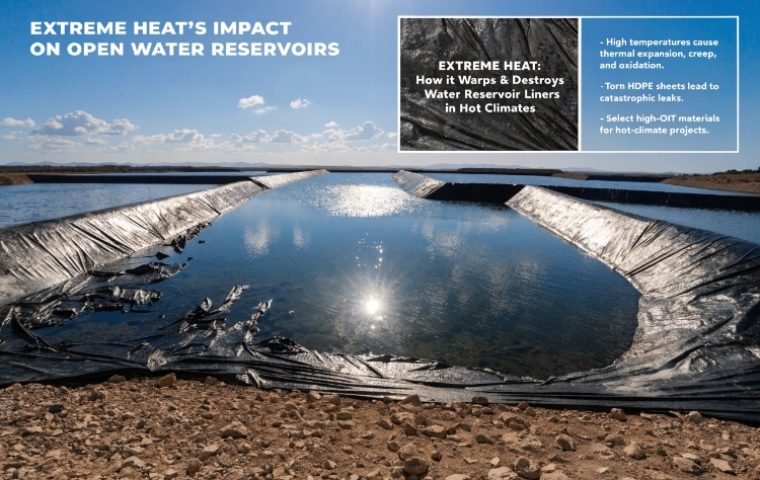
The chemistry of the leachate also plays a role. High temperature (from the exothermic leaching reaction) combined with high chemical concentration and high tensile stress (from head buildup) creates the perfect storm for accelerated aging.
Even the best resin has a finite Oxidation Induction Time (OIT). This is the measure of how many antioxidants are in the plastic to protect it. When a liner is stressed and heated by accumulated solution, the antioxidants are consumed much faster than in a cool, free-draining environment. Poor drainage literally "ages" the plastic faster, leading to premature embrittlement.
5. Leak Detection Systems: Why They Detect Failure, Not Prevent It
Many modern mines, especially in strictly regulated jurisdictions, install Leak Detection Systems (LDS). These typically consist of a secondary liner (bottom), a drainage net (geonet) in the middle, and a primary liner (top).
I often hear clients say: "We are safe because we have a double-lined system with leak detection."
This statement reveals a dangerous false sense of security regarding drainage design.
5.1 Detection Thresholds vs. Real Leakage
An LDS is designed to manage a certain volume of leakage (e.g., typically calculated as Liters per Hectare per Day, or Lphd). It triggers an alarm when this rate is exceeded.
However, consider the logic here: by the time the alarm triggers, the primary liner has already failed. The "failure chain" described in Section 3 has already completed its course. The LDS tells you that you have a problem; it does nothing to prevent the problem.
5.2 The False Sense of Security
If the primary drainage layer (above the primary liner) is allowed to clog or degrade, the hydraulic head on the primary liner rises. The primary liner eventually cracks due to the stress. The PLS then floods the LDS layer.
Now, you are relying on the secondary liner—which is often thinner (e.g., 1.0mm or 1.5mm) and has a less robust, thinner drainage capacity—to hold back the entire reservoir. Often, the secondary drainage layer becomes overwhelmed immediately by the high-volume burst from the primary failure, leading to rapid environmental discharge.
Good drainage design in the primary layer is the only true prevention. The LDS is merely an autopsy tool.
6. Operational Warning Signs That Precede Liner Failure
If you are an operator or a site engineer, how do you know if your liner is entering this "danger zone" before a catastrophic leak appears? You must look for signs of drainage distress, which are often subtle and misinterpreted as "process noise."
Here are the indicators that solution accumulation is occurring deep in your heap:
- Increases in PLS Residence Time: If you irrigate a new cell and it takes longer for the solution to appear at the ponds than your kinetic models predicted, the fluid is being stored (accumulating) in the pad.
- Rising Sump Levels Without Flow Increase: If the pore pressure transducers (piezometers) in the sump or vertical wells show rising levels, but the pump output hasn't increased, the transmissivity of the drainage system is resisting flow.
- Uneven Solution Recovery: "Dead zones" or inconsistent flows from different sectors of the pad suggest that parts of the drainage network are blocked, forcing solution to mound and migrate laterally to other areas.
- Localized Slope Softening: Wet spots, "weeping," or soft areas on the toe of the slope or the berms indicate that the phreatic surface inside the heap has risen dangerously high, likely intersecting the side slopes. This is a critical stability warning.
- Unexplained Changes in Leach Kinetics: If metal recovery drops unexpectedly, it may be because the bottom lifts are flooded (saturated). Saturated ore does not leach efficiently because oxygen cannot circulate. A drop in recovery is often the first sign of a flooded pad base.
7. Drainage Performance as Liner Risk Management
We need to reframe how the industry views the drainage layer. It is not just a conveyor belt for products (gold/copper); it is the primary safety system for the liner.
View the drainage layer as a pressure relief valve.
- Standard approach: "We need a drain to collect gold."
- Risk-aware approach: "We need a drain to ensure the hydraulic head on the liner never exceeds 0.5 meters, ensuring the liner remains in a low-stress state for its 20-year service life."
When you view drainage as liner protection, your procurement priorities change:
- Crush resistance: You select gravel or geocomposites not just for price, but for their ability to retain permeability under 200m of load.
- Chemical compatibility: You ensure pipes and nets are tested for resistance to scaling and chemical precipitation.
- Safety factors: You design drainage capacity for the "storm of the century" plus irrigation, not just average operating rates.
8. Conclusion – Liner Failures Start with Water, Not Plastic
In the high-stakes world of heap leaching, it is easy to fixate on the visible membrane. We inspect the welds, we test the coupons, and we worry about UV exposure. But the true enemy is buried deep under the pile, hidden in the dark.
Most operational liner failures are not failures of plastic manufacturing; they are failures of hydraulic management.
The sequence is clear and preventable:
- Drainage design is undervalued or maintenance is neglected.
- Transmissivity decreases over time due to creep or clogging.
- Solution accumulates, creating massive hydrostatic pressure (head).
- Pressure forces the liner against subgrade irregularities, causing stress cracking and puncture.
- High pressure drives massive leakage through small defects.
As a material supplier and solution provider, my advice to engineers and owners is simple: If you want to protect your liner, invest in your drainage.
Do not just check the specifications of the geomembrane. Scrutinize the long-term flow capacity of your drainage layer. Verify the degradation factors for your gravel or geonet. Ensure that your design keeps the liner in a "free-flow" environment, not a "pressurized" one.
By the time the leak alarm sounds, the damage is already done. Prevention begins with keeping the water moving.
Typical Root Causes Identified in Post-Failure Investigations
1. Pipe Collapse: Use of standard SDR pipes in deep heaps where heavy-wall or corrugated pipe was required, leading to structural failure and flow blockage.
2. Geotextile Clogging: Incorrect filtration aperture size ($O_{95}$) allowing ore fines to pass through and block the underlying geonet or gravel voids.
3. Biological/Chemical Clogging: Failure to account for algae or precipitate scaling (gypsum) in the long-term transmissivity calculations.
4. Insufficient Creep Reduction Factors: Using laboratory flow rates for geonets without applying 100-year creep reduction factors relevant to the stack height.
5. Valley-Fill Pinch Points: Inadequate redundancy in the central collection corridor of valley fills, where 100% of the solution is concentrated in 1% of the area.