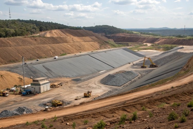
Na indústria de mineração, quando analisamos operações de lixiviação em pilha de baixo desempenho, a culpa é muitas vezes instintivamente colocada na mineralologia do minério, na qualidade da aglomeração ou na química lixiviante. No entanto, depois de investigar vários locais na América do Sul, África e Sudeste Asiático, descubro frequentemente que a causa raiz está abaixo da pilha – na camada de drenagem.
O camada de drenagem é frequentemente tratado como um componente secundário durante a fase de projeto – uma simples camada de cascalho e alguns tubos jogados no topo da geomembrana. Esta é uma simplificação perigosa. Na realidade, a camada de drenagem é o motor de recuperação da solução e o freio para a instabilidade dos taludes.
Se a camada de drenagem falhar, você enfrentará três crises agravadas: lagoa de solução (que mata a cinética de recuperação), pressão elevada da água nos poros (que ameaça falha catastrófica do talude), e aumento do risco de vazamento (não conformidade ambiental).
Este artigo explora por que o projeto da camada de drenagem não é apenas um detalhe, mas uma estratégia fundamental de gerenciamento de risco para projetos de lixiviação profunda.
O papel da camada de drenagem no desempenho da plataforma de lixiviação
A camada de drenagem é solicitada a desempenhar uma tarefa hercúlea: deve permanecer permeável e estruturalmente intacta enquanto estiver enterrada sob milhões de toneladas de minério durante décadas. É a interface onde os objetivos económicos do projeto (recuperação) colidem com as suas restrições físicas (carga e estabilidade).
2.1 Controlando o Fluxo de Solução e Prevenindo Alagamentos
A função mais imediata da camada de drenagem é evacuar o Solução de lixiviação para grávidas (PLS) tão rápido quanto chega à interface do liner.
Em um sistema bem projetado, a solução viaja verticalmente através do minério, atinge a camada de drenagem e se move horizontalmente para os tubos de coleta. No entanto, se o condutividade hidráulica da camada de drenagem é insuficiente, vemos o "efeito banheira" ou lagoa.
Por que a ponderação é fatal para as operações?
- Cinética de Recuperação: Ponding cria uma zona saturada na base da pilha. Isso interrompe o fluxo de oxigênio necessário para a biooxidação (em sulfetos de cobre ou ouro) e altera a química, muitas vezes reprecipitando os metais alvo antes de saírem da almofada.
- Receita atrasada: A drenagem lenta aumenta o tempo do ciclo de lixiviação. Se você não conseguir evacuar o PLS, não poderá processar o metal. Tenho visto operações em que uma drenagem deficiente acrescentou meses ao ciclo de recuperação, destruindo o Valor Presente Líquido (VAL) do projecto.
2.2 Protegendo o Sistema de Liner
Existe um equívoco de que apenas o revestimento da geomembrana é responsável pela contenção. Na prática, a contenção é uma função do revestimento mais a carga hidráulica agindo sobre ele.
De acordo com a Lei de Darcy, o vazamento através de um defeito na camisa é diretamente proporcional à carga hidráulica que a aciona.
- Se a sua drenagem mantém uma pressão <00,3 m, o vazamento é mínimo, mesmo com pequenos furos.
- Se a drenagem falhar e a altura manométrica subir para 5m ou 10m (comum em preenchimentos de vale com drenagem deficiente), a pressão motriz forçará grandes quantidades de PLS até mesmo através do menor defeito.
Ao manter a altura manométrica baixa, a camada de drenagem atua como a principal defesa contra a não conformidade ambiental.
2.3 Suportando estabilidade de heap sob carga
Esta é a função de segurança mais crítica. Uma pilha de lixiviação é essencialmente uma enorme estrutura geotécnica mantida unida por fricção.
O mecanismo de falha:
A estabilidade depende estresse eficaz ($\sigma'$) at the liner interface. The formula is $\sigma' = \sigma - u$, where $\sigma$ is the total weight of the ore and $u$ is the pore water pressure.
- Boa drenagem: A pressão da água nos poros ($u$) é próxima de zero. O estresse efetivo é alto. O atrito é maximizado.
- Drenagem bloqueada: Fluid builds up. $u$ increases. Effective stress ($\sigma'$) creates a "buoyancy" efeito, reduzindo drasticamente o atrito para perto de zero.
Eu revisei dados mostrando que em altas tensões de confinamento (por exemplo, abaixo de 150 m de minério), o ângulo de atrito da interface entre uma geomembrana texturizada e uma camada de GCL/solo pode cair de um nível estável 22° até um ponto crítico 5–7° se a interface ficar saturada e pressurizada. Uma superfície freática ascendente dentro da pilha é o principal precursor de deslizamentos catastróficos de encostas.
2.4 Permitindo Confiabilidade Operacional de Longo Prazo
Os projetos de mineração estão ficando mais longos e os montes estão cada vez mais profundos. Um sistema de drenagem que funciona no Ano 1 pode falhar no Ano 10 devido a fluência, esmagamento ou entupimento. Um design robusto antecipa a condição da almofada no fim da vida útil da mina, garantindo que as seções mais antigas da plataforma continuem a drenar mesmo quando novos elevadores são empilhados acima delas.
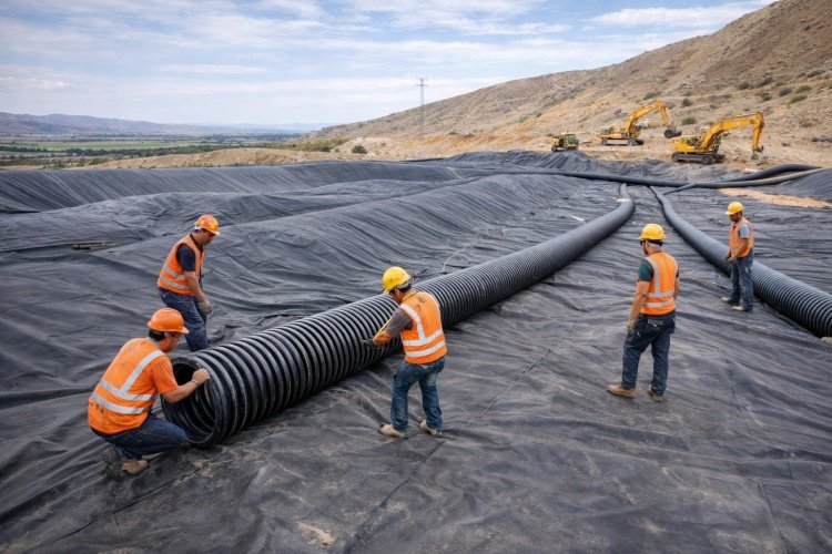
Camada de drenagem como um sistema, não como um único material
EPC contractors often request quotes for "drainage pipes" or "gravel processing" como itens isolados. Contudo, os operadores bem sucedidos vêem a camada de drenagem como um sistema composto onde cada componente depende do outro.
Um sistema funcional normalmente integra:
- Meio de drenagem granular (Overliner): O meio condutor primário. Deve ser triturado, peneirado e testado quanto à resistência a ácidos.
- Componentes de drenagem sintética: Geonetas ou geocompósitos utilizado em áreas onde o cascalho é escasso ou em encostas íngremes para auxiliar o fluxo.
- Camadas de Filtragem: Geotêxteis colocados sobre tubos ou entre o solo e o cascalho de drenagem para evitar que finos ofusquem o sistema.
- Tubulação de coleta: A rede arterial (tubos perfurados HDPE/LLDPE) que transporta fluido para o perímetro.
The "System" Filosofia:
Você pode ter um tubo HDPE perfurado da melhor qualidade, mas se for colocado diretamente sobre uma geomembrana sem almofada usando cascalho de alta tensão, o tubo perfurará o revestimento. Por outro lado, você pode ter cascalho excelente, mas se o geotêxtil de filtração ficar obstruído com precipitado químico, o cascalho se tornará inútil. O desempenho confiável vem do compatibilidade desses elementos.
Principais considerações de design que afetam diretamente o desempenho
Quando nos reunimos com consultores de engenharia para finalizar as especificações de um novo pad, nos concentramos em quatro campos de batalha técnicos onde a guerra pelo desempenho é ganha ou perdida.
4.1 Permeabilidade vs. Capacidade de Suporte de Carga
Existe um compromisso constante entre condutividade hidráulica e resistência à compressão.
- Alta permeabilidade: Requer tamanhos de partículas grandes e uniformes (por exemplo, cascalho de 25 a 38 mm) ou geonets de alta transmissividade.
- Rolamento de carga: Requer um solo bem graduado para distribuir o peso e evitar carregamento pontual.
Para pilhas profundas (>100m), we cannot simply use "open" gravel. Under 2MPa of vertical pressure, point loads from large stones can puncture the liner. The design must specify a "cushion" camada ou uma distribuição específica de tamanho de partícula (PSD) que protege o revestimento enquanto mantém uma permeabilidade saturada de pelo menos $1×10^{-4}$ m/s.
4.2 Resistência ao esmagamento, fluência e deformação
Muitos engenheiros calculam a resistência do tubo com base na profundidade padrão de enterramento. Na lixiviação em pilha, as cargas são extremas.
- Deformação do tubo: Sob alta sobrecarga, os tubos HDPE podem ovalizar. Se um tubo se comprimir significativamente, a sua capacidade de fluxo diminui e as perfurações podem fechar.
- Divisão de cascalho: O agregado fraco se transformará em pó sob alta carga (degradação). O que começou como uma camada de drenagem se transforma em uma camada de lodo de baixa permeabilidade após 5 anos, bloqueando o fluxo.
O Fator de fluência:
Synthetic materials (geonets and drainage pipes) suffer from compressive creep. A geonet might have high transmissivity in a 100-hour lab test, but under 10 years of constant load, it may lose 50-70% of its thickness and flow capacity. Designs must use "reduction factors" para dar conta desta realidade de 20 anos.
4.3 Riscos de entupimento e estratégia de filtragem
O entupimento é o assassino silencioso das camadas de drenagem. Vem de duas fontes:
- Entupimento físico: Migração de finos (argila/silte) do corpo mineral para a brita de drenagem.
- Entupimento Químico: Precipitação de sais (como gesso ou calcita) à medida que a química do PLS muda devido à evaporação ou mudanças de pH.
A prudent design includes a filtration strategy. This usually involves placing a non-woven geotextile filter or a distinct graded sand layer between the ore and the coarse drainage gravel. However, the filter itself must be designed not to clog. We often recommend specific "opening size" ($O_{95}$) critérios para geotêxteis com base na análise de partículas do minério.
4.4 Compatibilidade com Soluções de Lixiviação
O sistema de drenagem deve sobreviver ao ambiente químico.
- Lixiviação de Cobre: Altamente ácido (ácido sulfúrico). Cascalhos pesados à base de carbonato se dissolverão, neutralizando quimicamente o ácido (custando dinheiro) e colapsando fisicamente o espaço vazio de drenagem.
- Lixiviação de ouro: Alcalino (cianeto). Geralmente menos agressivo ao cascalho, mas polímeros específicos em tubos ou geotêxteis devem ser verificados quanto à estabilidade a longo prazo em ambientes de pH elevado.
Armadilhas comuns no projeto da camada de drenagem observadas em projetos de lixiviação em pilha
Tendo fornecido materiais para projetos que exigiam trabalhos corretivos, cataloguei os erros de projeto mais comuns que levam ao fracasso.
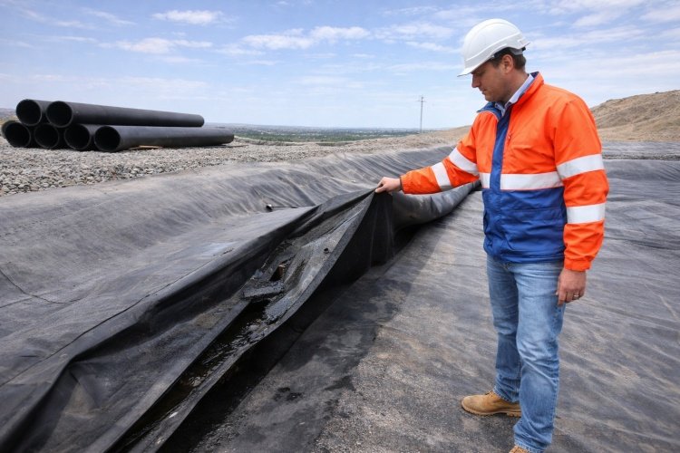
1. The "Pipe-on-Liner" Erro (concentração de estresse)
O erro mais grave é colocar tubos de drenagem diretamente no revestimento da geomembrana.
- O problema: O tubo é um objeto rígido. Sob o imenso peso da pilha, o tubo é empurrado para dentro do revestimento. Estudos mostram que as concentrações de tensão ao redor do tubo podem atingir 125% da pressão média de sobrecarga.
- A consequência: Isto cria uma linha de alta tensão onde o revestimento é esticado e afinado. É exatamente aqui que o stress cracking se inicia.
- A correção: Os tubos devem ser colocados em valas ou sobre uma almofada de areia/geotêxtil, nunca diretamente sobre a barreira primária.
2. Subdimensionamento da Rede de Cobrança
Tentar poupar dinheiro aumentando o espaçamento entre tubos de recolha (por exemplo, promovendo um espaçamento de 10m em vez de 2m).
- O resultado: O PLS precisa se deslocar muito horizontalmente através do cascalho para encontrar um cano. Isto aumenta a carga hidráulica entre os tubos (montagem), criando bolsas de alta pressão e instabilidade.
- Meta: Nosso objetivo é uma rede densa (alta densidade de drenagem) para manter a carga líquida uniformemente baixa (<00,3m).
3. Ignoring the "Valley" Efeito
Nas lixiviações de aterro de vale, a topografia natural canaliza toda a solução para o eixo de drenagem central distinto.
- O volume de líquido aqui é enorme em comparação com uma almofada plana.
- Standard pipe designs often fail to handle this focused flow, leading to submerged pipes and hydraulic heads of 10m+, which creates a "slip plane" bem no centro do vale.
Impactos operacionais e econômicos do projeto adequado da camada de drenagem
Por que o proprietário do projeto deveria aprovar um orçamento mais alto para um sistema de drenagem premium (por exemplo, espaçamento menor entre tubos, cascalho de melhor qualidade, geotêxteis de proteção)? Porque o ROI é calculado em capacidade de recuperação e prevenção de riscos.
1. Recuperação Maximizada de Metal:
Uma camada de drenagem altamente eficiente garante que cada litro de PLS bombeado para o topo da pilha seja recuperado na parte inferior. A redução do vazamento diário de 10.000 litros para quase zero impacta diretamente a produção anual de ouro/cobre.
2. Garantia de estabilidade de taludes:
Ao manter uma superfície freática baixa, o ângulo de atrito efetivo na interface do revestimento é mantido. Isto permite ângulos de inclinação mais acentuados ou empilhamento mais alto, maximizando a capacidade de tonelagem da área ocupada pela plataforma.
3. Manutenção e tempo de inatividade reduzidos:
Fixing a crushed pipe under 80 meters of ore is impossible. Fixing a clogged exit drain requires shutting down irrigation. A robust design is a "install and forget" sistema que reduz o OPEX ao longo da vida útil da mina.
Conclusão:
O custo de uma camada de drenagem atualizada (por exemplo, adicionando uma camada de transmissividade geocomposta ou atualizando a classificação SDR do tubo) é geralmente inferior a 1% do CAPEX total do projeto. O custo de uma falha de talude ou de uma queda de 10% na recuperação é catastrófico.
Por que as primeiras decisões de design são importantes
In heap leaching, there is no "Plan B" para o sistema de revestimento inferior. Uma vez empilhado o primeiro levantamento de minério, a camada de drenagem fica inacessível.
We often see projects try to "value engineer" (redução de custos) na camada de drenagem durante a fase de aquisição. Eles mudam de tubos de resina virgem para tubos de qualidade comercial ou removem o geotêxtil de proteção.
- Essas decisões são permanentes.
- Você não pode instalar retroativamente uma camada de filtro depois que os finos obstruírem o cascalho.
- Você não pode atualizar a resistência do tubo quando a pilha tiver 50 m de altura e os tubos estiverem achatados.
Envolva a experiência desde o início:
Trabalhar com fornecedores de materiais experientes e empresas de engenharia durante as fases de viabilidade e projeto detalhado ajuda a otimizar o sistema. Podemos simular a fluência a longo prazo de geotêxteis ou a capacidade de fluxo de tubos sob carga antes você os compra.
Conclusão
O projeto da camada de drenagem é um fator crítico no desempenho da plataforma de lixiviação, igual em importância ao próprio revestimento. Atua como sistema circulatório da mina, facilitando a receita (fluxo PLS) e segurança essencial (estabilidade).
Projetos de mineração bem-sucedidos reconhecem que a camada de drenagem é um sistema, não uma mercadoria. Eles priorizam:
- Cabeça Hidráulica Baixa: Mantendo os níveis de líquidos <00,3 m para maximizar a estabilidade e minimizar vazamentos.
- Proteção contra estresse: Protegendo o revestimento contra concentrações de tubos e perfurações de cascalho.
- Durabilidade a longo prazo: Contabilização de fluência, esmagamento e entupimento químico ao longo de décadas.
No Especialista em Impermeabilidade, entendemos as interações entre geomembranas, geotêxteis e tubulações de drenagem em ambientes de alta carga. Não fornecemos apenas rolos de plástico; auxiliamos na configuração de um sistema de drenagem que garante que sua plataforma de lixiviação funcione de maneira confiável desde o primeiro dia de irrigação até o último dia de fechamento.
O design do seu projeto está sendo otimizado para recuperação e estabilidade a longo prazo?
Entre em contato com nossa equipe técnica para discutir como nossas soluções geossintéticas podem ser integradas ao projeto da sua camada de drenagem para minimizar riscos e maximizar a eficiência operacional.