Your anaerobic digestion plant is an energy factory, but for many operators, a "silent thief" is stealing revenue every single hour. You might see it in gas flow meters that consistently read lower than your biological models predict. You might smell it when the wind changes direction. Or you might only discover it during a safety audit. This thief is gas leakage.
While catastrophic failures make the headlines, it is the slow, pervasive leakage of methane that quietly undermines the profitability of biogas projects worldwide. Identifying the source is rarely as simple as finding a hole in the plastic. It requires a forensic understanding of how these systems are built, how they age, and how they react to operational stress.
Common causes of gas leakage in biogas liner systems include improper seam welding parameters, inadequate sealing around pipe penetrations, chemical degradation from H₂S exposure, and mechanical fatigue caused by pressure fluctuations. Leakage is rarely due to the geomembrane material itself, but rather failures in installation details, quality control (QA/QC), and long-term operational maintenance.

From our experience supplying and overseeing projects across global markets, we have found that 90% of leakage issues are preventable. However, prevention starts with understanding that a "leak" is almost never just a hole—it is a symptom of a systemic oversight.
Why Gas Leakage Is Often a System Problem, Not a Material Defect
When a leak is detected, the immediate reaction from the project owner is often to blame the material supplier. "This geomembrane is defective," is a phrase we hear before any investigation has even started. While manufacturing defects are possible, in the modern geosynthetics industry, they are statistically the least likely cause of gas loss.
The production of high-quality HDPE (High-Density Polyethylene) or LLDPE (Linear Low-Density Polyethylene) is a highly automated, rigidly controlled process. If you are buying from a reputable manufacturer meeting GM13 or GM17 standards, the likelihood of a pinhole in the middle of a roll is infinitesimal. The reality is far more complex: the leakage is usually a failure of the system, not the product.
The Gap Between Design Assumptions and Operating Reality
Design engineers work in a world of ideal conditions. In CAD drawings, the subgrade is perfectly flat, the temperature is a constant 20°C, and the installation team works with robotic precision.
In the real world, the subgrade settles unevenly, creating stress points. Ambient temperatures on a job site can swing from 5°C in the morning to 35°C in the afternoon, causing the massive sheets of plastic to expand and contract significantly while they are being installed. Wind gusts lift panels before they are ballasted.
Leakage often originates in this gap between theory and reality. For example, a design might call for a pipe penetration to be sealed with a standard boot. However, on-site, that pipe might be coming in at a slight angle rather than perfectly perpendicular. If the installation team forces a standard solution onto a non-standard reality without adapting the detail, a stress point is born. That stress point will eventually become a leak.
Why “Good Material” Alone Cannot Prevent Leakage
There is a dangerous misconception in our industry that buying the "best" spec material provides immunity against leaks. We often see procurement teams fight hard for a slightly thicker material or a specific resin blend, believing this is their insurance policy.
Think of it like building a house. You can buy the finest bricks in the world, but if the mason uses poor quality mortar or lays the bricks crookedly, the wall will fail. In a biogas system, the geomembrane is the brick. The welding, the penetration details, and the mechanical attachments are the mortar.
Gas, particularly methane, is a small molecule that is incredibly elusive. It acts like a fluid under pressure, constantly seeking the path of least resistance. That path is never through the molecular structure of a sound HDPE sheet. It is through the places where the sheet was cut, joined, or punctured during construction. Therefore, leak prevention is 10% material selection and 90% execution strategy.
Seam-Related Leakage: The Most Common Weak Point
If you were to analyze the data from hundreds of leak detection surveys on biogas covers, the data points would cluster overwhelmingly in one specific area: the seams.
A typical anaerobic lagoon cover involves tens of thousands of linear meters of field seams. These are created by technicians crawling on their hands and knees, operating a wedge welder that heats the plastic to over 300°C to fuse the sheets together. It is a manual manufacturing process performed in an uncontrolled environment. It is statistically inevitable that this is where your vulnerabilities lie.
Poor Welding Practices and Inadequate Quality Control
The physics of a geomembrane weld are exacting. For two sheets of polyethylene to fuse into a single, monolithic, gas-tight unit, three variables must be perfectly balanced: temperature, speed, and pressure.
- Temperature: If the wedge is too cool, you get a "cold weld." The sheets stick together, but the molecules don't interlock. Under the first pressure test, it might hold. But once the cover inflates and peel forces are applied, the layers separate. Conversely, if it's too hot, the polymer degrades and becomes brittle, cracking under stress later.
- Preparation: This is the most overlooked step. Dust, moisture, or even a fingerprint on the weld track can prevent fusion. On a muddy job site, keeping the overlap clean requires discipline that tired crews sometimes lack.
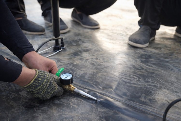
The failure here is often not the welding itself, but the Quality Control (QC).
In liquid containment, a small flaw in a double-track weld might not leak water. But in gas containment, that same flaw is a highway for methane. We frequently see projects where the installer performed air channel testing (pressurizing the gap between the two weld tracks) but failed to hold the pressure long enough or ignored a slow pressure drop. A "close enough" mentality in QC is the primary driver of seam leakage.
Long-Term Stress on Seams Under Gas Pressure
Even a weld that passes inspection on Day 1 can fail on Day 1,000. This is due to a phenomenon known as creep or stress cracking.
A generic landfill liner sits passively on the ground. A biogas cover, however, is a dynamic structure. As gas is produced, the cover inflates or "balloons." This inflation puts "hoop stress" on the material—pulling it tight like the skin of a drum. This tension is not applied to the solid sheet alone; it pulls directly on the seams.
If a seam has a microscopic imperfection—a tiny air bubble or a speck of dust—the constant tension creates a stress concentration point. Over months and years of inflating (daytime) and deflating (nighttime or during gas off-take), this stress works to enlarge that imperfection. Eventually, the weld peels open or cracks. This is why "peel strength" and "shear strength" in your material specs are not just numbers; they are predictors of whether your plant will be leaking in five years.
Penetrations, Interfaces, and Details That Commonly Leak
While seams are the most frequent location of leaks, penetrations are often the location of the largest volume leaks. A penetration is any point where a foreign object—a pipe, a mixer shaft, a concrete column, or a submersible pump cable—passes through the liner.
Geometrically, passing a round pipe through a flat sheet creates a complex sealing challenge. It requires cutting the liner and rebuilding the seal manually. These are the hardest parts of the installation to get right.
Pipe Boots, Flanges, and Embedded Components
The standard solution for sealing a pipe is a "pipe boot"—a sleeve made of geomembrane that is welded to the liner and clamped to the pipe. Here is why they fail:
- The Clamp Seal: The boots are typically sealed to the pipe using a stainless steel band clamp and a sealant (mastic). But HDPE liner and steel pipes expand and contract at very different rates. In summer, the liner expands; in winter, it shrinks. This cyclical movement often loosens the clamp or degrades the mastic, creating a gap.
- Field Fabrication Issues: Pre-fabricated factory boots are excellent, but often pipes are in odd locations, forcing installers to "field fabricate" a boot. This involves excessive hand welding (extrusion welding). Extrusion welding is highly operator-dependent. Only the most skilled technicians can create a 100% gas-tight extrusion weld, especially on vertical surfaces or the underside of a pipe.
- Vibration: Pumps and mixers vibrate. If the pipe boot is not designed with a flexible isolation joint, that vibration is transferred directly to the weld, causing fatigue cracking over time.
Anchoring Systems and Edge Terminations
The perimeter of your digester is another major leak risk. The cover must be anchored to the ground or the concrete wall to create a seal.
In earth-banked lagoons, this is usually done via an "anchor trench." The liner is buried in a trench and backfilled with soil. The assumption is that the soil weight creates the seal. However, soil is porous. If the trench is not designed with a specific gas-lock mechanism (like a clay plug or a compacted bentonite layer), gas can migrate underneath the liner, travel through the soil matrix of the anchor trench, and vent to the atmosphere meters away from the lagoon. We have seen sites where the grass is dead in a ring around the lagoon—a tell-tale sign of methane migrating through the anchor trench soil.
For concrete tanks, the liner assumes a mechanical seal using a stainless steel batten bar. Leakage here occurs if the concrete surface is not perfectly smooth (spalling or honeycomb voids) or if the gasket material behind the batten bar degrades.
Material Aging and Chemical Exposure Effects
We often think of plastic as eternal, but in the harsh environment of an anaerobic digester, time is an enemy. The material you install today is not the same material you will have in ten years. Chemical and environmental attacks slowly strip away the liner's defenses.
Exposure to H₂S, Condensate, and Acidic Environments
Biogas is not just methane and CO₂. It contains a cocktail of aggressive trace gases, most notably Hydrogen Sulfide (H₂S).
In the headspace of the digester (the area between the liquid and the cover), warm biogas hits the cooler cover material and condenses. This moisture reacts with the H₂S and CO₂ to form a mild sulfuric and carbonic acid solution. This acidic condensate clings to the underside of the liner 24/7.
While polyethylene itself is generally resistant to acids, the additives within the plastic—specifically the antioxidants and UV stabilizers—can be depleted by this chemical attack. This process is called "oxidative induction time (OIT) depletion." Once the antioxidants are consumed, the polymer chain itself begins to break down. The material becomes brittle. A brittle liner cannot flex with gas pressure changes; instead, it develops micro-cracks that allow gas to permeate or leak.
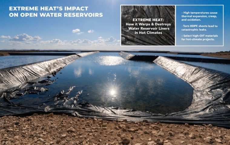
UV, Temperature Cycling, and Long-Term Degradation
The top side of the cover faces a different enemy: the sun.
UV radiation is incredibly destructive to polymer chains. High-quality geomembranes are loaded with carbon black (usually 2-3%) to absorb this radiation. However, in regions with intense solar exposure, the surface temperature of a black liner can reach 70°C or 80°C.
This extreme heat does two things:
- Accelerated Aging: Heat speeds up every chemical reaction, including the depletion of stabilizers mentioned above.
- Thermal Fatigue: The cover expands massively during the day (creating wrinkles) and shrinks tight at night. At the top of the wrinkles, the material is bent back and forth daily. This "thermal cycling" can cause Stress Cracking (SC) along the ridges of wrinkles after several years. These cracks are often invisible to the naked eye until the cover is pressurized, at which point they open up and leak.
Operational Factors That Increase Leakage Risk
Sometimes, the system is built perfectly, and the material is flawless, but the way the plant is operated induces leakage. The operator plays a crucial role in maintaining the "gas-tight" status of the facility.
Uncontrolled Pressure Fluctuations
A geomembrane cover is designed to operate within a specific pressure range—typically very low (e.g., 2 to 5 millibars).
If the gas utilization equipment (CHP engine or flare) trips offline, gas pressure builds up instantly. If the safety pressure relief valves (PRVs) are stuck, undersized, or set incorrectly, the pressure under the cover can spike. This over-pressurization stretches the liner beyond its yield point.
While polyethylene is ductile and can stretch, the seams cannot. A pressure spike often creates micro-tears in the heat-affected zone next to the welds. The cover might look fine once the pressure returns to normal, but the damage is done. The integrity of the gas barrier has been compromised.
Maintenance Activities and Accidental Damage
We have visited sites where the primary cause of leakage was clearly "human error" during maintenance.
- Mixer Service: Pulling heavy submersible mixers up through service hatches often involves dragging chains or cables across the liner. One sharp edge on a chain link can scour or punture the material.
- Walking on Covers: Personnel walking on floating covers to inspect ports or clear debris can cause damage if they have stones stuck in their boot treads.
- Sampling Boats: In large lagoons, operators sometimes use small boats to take sludge samples. We have seen leaks caused by the propellers of these boats slicing the liner when the liquid level was lower than expected, or by the boat hull scraping against the side slopes.
These "accidental" punctures are often small and go unnoticed immediately, but they are direct vents for gas to escape.
Why Leakage Often Appears Years After Commissioning
It is a frustrating paradox: a facility passes its initial handover pressure test with flying colors, but five years later, it is leaking significantly. Why?
Cumulative Fatigue and Progressive Failure
Leakage is rarely an "on/off" event. It is a progressive deterioration.
Think of a paperclip. You can bend it once, and it’s fine. Bend it ten times, and it’s fine. But bend it fifty times, and it snaps.
A biogas liner is subjected to these cycles daily. Wind flutter, pressure inflation/deflation, and thermal expansion/contraction are all bending that paperclip. A weld that was 90% good at installation might survive the first year. But that 10% weakness is a stress concentrator. Over four years of operational fatigue, that weakness propagates into a crack.
This is why Stress Crack Resistance (SCR) is one of the most critical values on a data sheet. We always recommend materials that exceed the standard GRI-GM13 requirements for SCR (typically >500 hours) because high SCR is essentially "fatigue insurance" for your project.
Early Warning Signs Often Overlooked
Often, the system gives warnings before a major leak impacts revenue, but operators miss them because they don't know what to look for:
- "Waving" Covers: If one section of a floating cover is flapping vigorously in the wind while the rest is taut, it suggests that section has lost internal pressure—likely a leak.
- Vegetation Changes: A patch of yellow or dead grass on the slope near the anchor trench usually indicates methane displacing oxygen in the soil.
- Smell: The human nose is incredibly sensitive to H₂S. If you smell "rotten eggs" consistently in one corner of the lagoon, trust your nose—there is a leak nearby.
Conclusion: Preventing Gas Leakage Requires System-Level Thinking
If you take one thing away from this guide, let it be this: Gas leakage is not a product failure; it is a system failure.
You cannot solve leakage by simply buying a thicker liner or a more expensive brand of plastic. You solve it by adopting a holistic approach that respects the unforgiving nature of gas containment.
- Design for Reality: Detail your penetrations and anchor trenches for movement and settlement, not just for static drawings.
- Enforce Rigorous QC: Do not accept "visual inspection" for seams. Demand air channel testing and vacuum box testing on 100% of the welds.
- Respect the Chemistry: Ensure your material is formulated with high-performance antioxidants and UV stabilizers designed specifically for the aggressive biogas environment.
- Operate with Care: Train your team to treat the liner as a delicate piece of critical infrastructure, not just a ground cover.
At Waterproof Specialist, we have seen that the most profitable biogas projects are those where the owners and contractors treat the liner system with the same level of engineering respect as the generator engine. When you close the gap between design and reality, you stop the silent thief and keep your energy revenue where it belongs—in your pipes, not in the atmosphere.