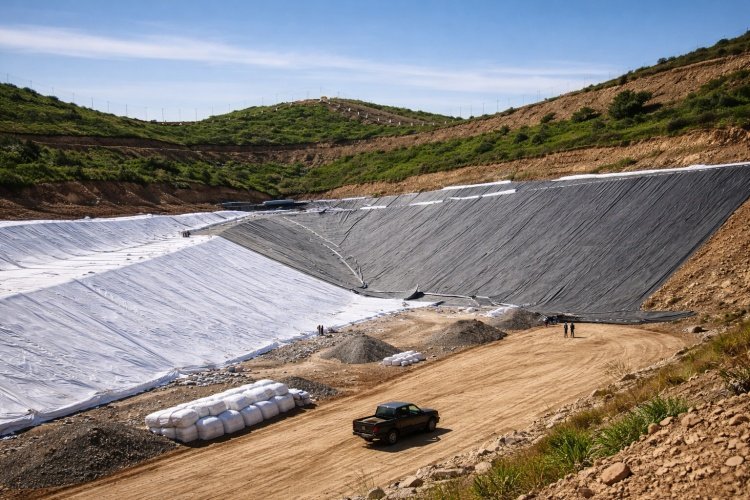
Stacking massive ore heaps is fundamental to modern mining, but it places extreme stress on the underlying containment system. The immense weight, sharp angles, and long-term loads create a high-risk environment for the geomembrane liner, which is the last line of defense against environmental contamination. A failure here is not a minor setback; it's a critical operational and financial threat.
This article explains the primary ways ore stacking can cause serious and often irreversible damage to geomembrane liners. More importantly, we outline the proven engineering and installation practices required to prevent these failures and ensure the long-term integrity of your heap leach pad or ore stockpile.
Understanding the mechanisms of damage is the first and most important step toward designing a liner system that is built to last.
What Is Ore Stacking in Mining Applications?
In this context, ore stacking refers to the process of placing large volumes of mined ore onto a prepared surface, typically a geomembrane-lined pad. This is a core activity in applications like heap leach pads, permanent ore stockpiles, and temporary storage areas for tailings or processed materials.
This process is uniquely challenging for a liner system due to a combination of factors:
- High Unit Loads: Ore heaps can reach heights of over 100 meters, exerting immense, sustained pressure on the liner system, often exceeding 2,000 kPa (or 290 psi).
- Long-Term Loading: Unlike temporary construction loads, the weight of the ore is applied continuously for months, years, or even decades.
- Dynamic and Abrasive Placement: The process of dumping, pushing, and spreading ore with heavy machinery creates significant impact, shear, and abrasion forces on the surface beneath.
These conditions are far more severe than those found in typical civil containment applications like landfills or ponds. This is why the design and protection of a mining liner system require a much higher level of engineering scrutiny.
Main Mechanisms by Which Ore Stacking Damages Geomembranes
Geomembrane damage from ore stacking is rarely caused by a single, dramatic event. It is usually the result of one or more interacting mechanisms that progressively weaken the liner until a leak occurs. The table below summarizes the key failure modes before we explore each one in detail.
| Damage Mechanism | Primary Cause | Resulting Liner Damage |
|---|---|---|
| Puncture | Sharp, angular ore creating high point loads. | Micro-holes, tears, and full-thickness punctures. |
| Creep & Deformation | Sustained, high static load from the ore heap. | Gradual thinning, loss of strength, and stress cracking. |
| Shear & Abrasion | Ore movement and sliding during placement. | Surface wear, gouging, and peeling of welded seams. |
| Subgrade Stress | Unprepared subgrade with sharp objects or unevenness. | Punctures from below and high tensile stress from settlement. |
Puncture Damage from Angular Ore
This is the most direct and intuitive failure mechanism. The ore, by its very nature, is often crushed and contains thousands of sharp, angular edges. When this material is placed on the liner, these sharp points act like needles. The localized stress at the tip of a single sharp rock can be many times greater than the average pressure from the heap. This concentrated force can easily exceed the liner’s puncture resistance, creating micro-holes or full-thickness punctures. This risk is highest with thinner geomembranes and when a proper protective layer is absent.
Creep and Long-Term Deformation under Static Load
HDPE, the most common material for heap leach liners, is a viscoelastic material. This means that under a constant, sustained load, it will slowly deform and stretch over time—a phenomenon known as creep. The immense weight of the ore heap is a perfect condition for inducing creep. Over months and years, this can cause the geomembrane to thin out in high-stress areas, reducing its thickness and, consequently, its resistance to puncture and chemical attack. This effect is significantly accelerated by higher temperatures, which can occur at the base of a heap due to exothermic leaching reactions.
Shear and Abrasion during Ore Placement
The process of building the ore heap is dynamic. As ore is dumped from trucks or conveyors and then spread by bulldozers, it slides and grinds against the surface below it. This creates powerful shear forces and abrasion that can physically wear down the liner's surface. The welded seams are particularly vulnerable to these shear forces. If a seam is not perfectly welded, the stress from moving ore can cause it to peel open, creating a long, linear leak path.
Subgrade-Related Stress Amplification
The threat doesn't only come from above. If the subgrade foundation beneath the geomembrane was not properly prepared, it can become a major source of failure. A single sharp rock or piece of debris left in the subgrade acts as an anvil. The pressure from the ore heap above presses the liner down onto this sharp point, effectively amplifying the stress and guaranteeing a puncture from below. Similarly, an uneven or poorly compacted subgrade can lead to differential settlement, which creates high tensile stresses that can tear the liner.
Typical Consequences of Geomembrane Failure in Ore Stacking Areas
When a geomembrane liner fails under an ore heap, the consequences are severe and costly. It is crucial to understand that these failures are not just about material defects; they are system failures with significant business implications.
- Environmental Contamination: This is the most serious consequence. Leaking process solutions can contaminate soil and groundwater, leading to long-term environmental liability and complex remediation efforts.
- Regulatory Non-Compliance: A leak is a breach of environmental permits, often resulting in heavy fines, mandatory operational changes, and even project shutdowns by regulatory agencies.
- High Remediation Costs: Locating and repairing a leak buried under thousands of tons of ore is an extremely difficult and expensive undertaking, often costing millions of dollars.
- Operational Downtime: Repair activities can require halting or scaling back production, directly impacting project revenue and profitability.
- Reputational and ESG Risk: A significant environmental incident can damage a company's reputation with investors, local communities, and stakeholders, impacting its social license to operate and its ESG (Environmental, Social, and Governance) ratings.
How to Prevent Ore Stacking Damage to Geomembrane Liners
The good news is that these failure mechanisms are well understood, and proven prevention strategies exist. Preventing damage requires a holistic, system-based approach that starts long before the first ton of ore is placed. The following table connects the key risks to their primary prevention strategies, which are then detailed below.
| Area of Concern | Prevention Strategy | Key Specification / Action |
|---|---|---|
| Puncture & Abrasion | Use of protective layers. | Place a nonwoven geotextile (800–1200 g/m²) directly on the geomembrane. |
| Long-Term Load & Creep | Select a robust geomembrane. | Specify HDPE with a thickness of ≥1.5 mm (2.0 mm for high-load zones). |
| Subgrade Puncture | Meticulous subgrade preparation. | Clear all sharp objects; ensure the surface is smooth and uniformly compacted. |
| Installation Defects | Implement strict QA/QC. | Use certified installers; perform 100% non-destructive testing on all field seams. |
Select the Right Geomembrane Thickness and Material
For heap leach pads and major stockpiles, a minimum thickness of 1.5 mm (60 mil) HDPE is standard practice. In areas subjected to very high loads from tall ore stacks or heavy equipment, specifying a 2.0 mm (80 mil) HDPE geomembrane is a wise investment. The extra thickness provides a significantly higher factor of safety against both puncture and the long-term effects of creep.
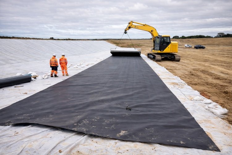
Use Proper Protective Layers Above the Geomembrane
The geomembrane should never be the primary component resisting mechanical damage. A robust protective layer is essential. The most effective solution is a thick, needle-punched الجيوتكستيل غير المنسوج placed directly on top of the geomembrane. For mining applications, we typically recommend a geotextile with a mass of 800 g/m² to 1200 g/m². This thick, felt-like cushion absorbs impact energy and distributes point loads from sharp rocks, effectively protecting the liner from puncture.
Improve Subgrade Preparation
Prevention starts from the ground up. The subgrade must be meticulously prepared by removing all rocks, roots, and sharp objects larger than a small gravel. The surface must be graded smooth and compacted to a uniform density to prevent differential settlement. This simple but critical step eliminates the risk of puncture from below.
Ensure High-Quality Installation and Welding
The integrity of the liner system depends on the quality of its installation. It is critical to use certified and experienced installation contractors who follow strict QA/QC protocols. All seams should be created using dual-track thermal welders, and 100% of the field seams must be non-destructively tested using methods like air pressure testing or vacuum box testing to ensure they are leak-free.
Adopt a System-Based Design
A geomembrane does not work in isolation. The key to preventing ore stacking damage is to think in terms of a complete liner system. This system should integrate three core functions:
- Containment: The impermeable geomembrane.
- حماية: The thick geotextile cushion and proper subgrade.
- الصرف: The leachate collection system that efficiently removes liquid and reduces hydraulic head on the liner.
Only when all three components are designed to work together can the system achieve long-term durability.
Why Proper Geomembrane Selection Matters for Mining Projects
Not all mining projects are the same, and a one-size-fits-all approach to liner selection can lead to either over-engineering (unnecessary cost) or under-engineering (unacceptable risk). The height of the ore stack, the angularity of the ore, the operational temperatures, and the chemistry of the leach solution all influence the optimal choice of geomembrane material and thickness.
This is where technical support and application experience become invaluable. An experienced supplier can help you evaluate these project-specific risks and recommend a liner system that is both safe and cost-effective. In long-term mining projects, making the right selection in the design phase is always exponentially cheaper than attempting to repair a failure later on.
Conclusion: Reducing Risk Starts with Understanding the Damage Mechanism
Ore stacking is undeniably one of the most demanding applications for a geomembrane liner. The damage that occurs is rarely from a single cause but rather a combination of mechanical, chemical, and thermal stresses acting over time.
A liner failure is not an inevitability; it is a preventable event. Understanding how ore stacking damages geomembrane liners is the first step toward effective prevention. By implementing a system-based design that includes a robust liner, proper protection layers, meticulous subgrade preparation, and high-quality installation, you can confidently mitigate these risks and build a containment system that ensures the safety and profitability of your operation.
If you are planning a heap leach pad or ore stockpile project, contact us for geomembrane liner selection and protection system recommendations. Our technical team can help you design a safer and more durable liner system for your specific mining application.