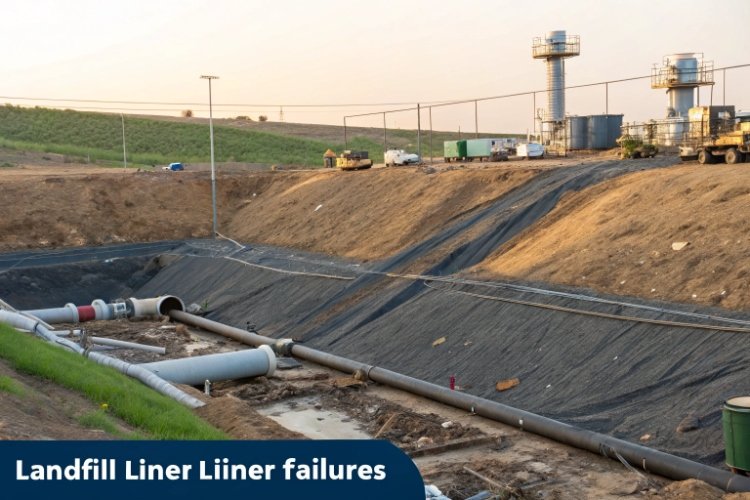
A landfill liner is more than a plastic sheet; it is the single most critical barrier protecting our environment from contamination. When this barrier is breached, the consequences can be catastrophic and permanent, leading to polluted groundwater, unstable landmasses, and cleanup costs that can dwarf the initial construction budget. Understanding why liners fail is the first step to preventing a disaster.
Effective containment is the cornerstone of modern landfill engineering. Yet, failures still occur, and they are rarely caused by a single, dramatic event. More often, they are the result of a chain reaction of smaller, interconnected issues. This guide breaks down the common types of landfill liner failures, explores their root causes, and provides a comprehensive framework for prevention through superior design, materials, and operational diligence.
First, let's establish a clear definition of what constitutes a "failure."
What Is a Landfill Liner Failure?
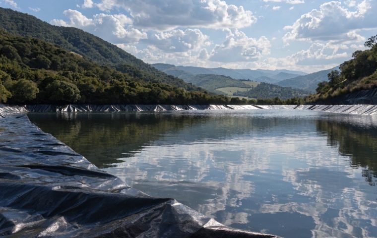
A landfill liner failure is any breach, degradation, or underperformance of the containment system that allows leachate—the contaminated liquid that drains from waste—to escape into the underlying soil and groundwater. This can range from a tiny pinhole to a massive slope stability failure. Landfill liner systems are typically complex, multi-layered structures designed for redundancy.
Common Liner Materials
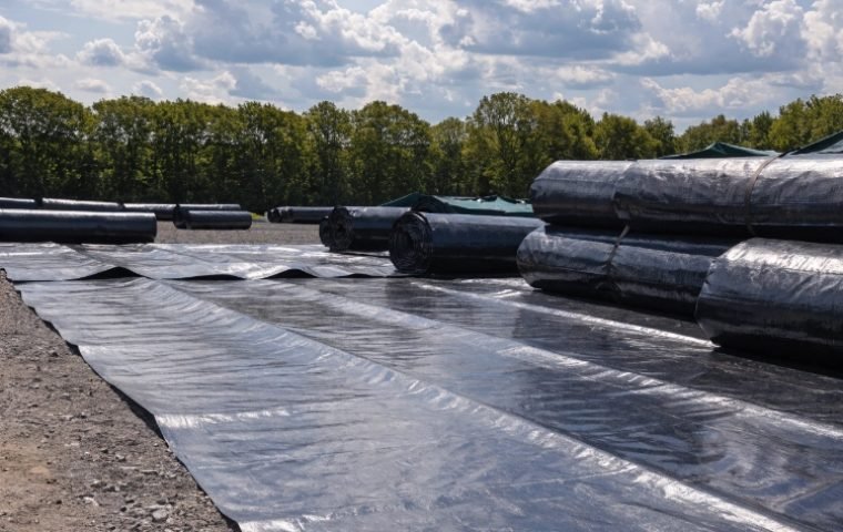
- غشاء أرضي HDPE: High-Density Polyethylene is the industry standard due to its excellent chemical resistance, durability, and low permeability. It is typically used in thicknesses of 1.5 mm to 2.0 mm.
- GCL (Geosynthetic Clay Liner): A GCL consists of a thin layer of sodium bentonite clay sandwiched between two geotextiles. When hydrated, the clay swells to create a highly effective hydraulic barrier.
- Composite Liner Systems: Modern landfills use a composite system, placing an HDPE geomembrane directly on top of a GCL or a compacted clay layer. This combination provides a significantly higher level of protection than either component alone.
Common Landfill Liner Failures
These are the direct, observable symptoms of a failing liner system.
Puncture and Mechanical Damage
This is the most straightforward failure type. It occurs when the geomembrane is physically torn or perforated. The common culprits include:
- Sharp rocks, roots, or debris left in the subgrade.
- Careless placement of the sharp-edged gravel drainage layer.
- Heavy equipment driving directly on the liner.
- Punctures from waste objects during the initial filling operations.
Seam and Welding Failure
The seams where liner panels are joined are the most vulnerable points in the entire system. Welds can fail due to:
- Improper Welding Parameters: Using a welding machine at the wrong temperature, speed, or pressure for the ambient conditions.
- Contamination: Welding on surfaces contaminated with dust, moisture, or mud, which prevents a proper molecular bond from forming.
- Lack of Quality Control: Failure to perform rigorous testing on 100% of the field seams to identify and repair faulty welds.
Chemical Degradation of Liner Materials
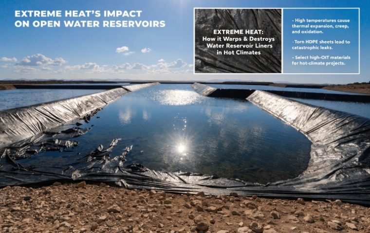
While HDPE is highly resilient, it is not completely immune to all chemicals over a multi-decade lifespan. Aggressive, non-typical waste streams containing certain industrial solvents or aromatic hydrocarbons can cause the polymer to soften, swell, or become brittle over time, compromising its integrity.
Stress Cracking and Tensile Failure
This is a more insidious, long-term failure mechanism.
- Differential Settlement: As the waste decomposes and consolidates, it settles unevenly. This can stretch the geomembrane over high and low points, creating immense tensile stress in the material.
- التمدد الحراري: The liner expands in the heat of the day and contracts at night. This daily cycling can fatigue the material, especially in areas where it is under tension. Over years, these stresses can lead to the formation of slow-growing cracks, a phenomenon known as Environmental Stress Cracking (ESC).
Main Causes Behind Landfill Liner Failures
While the failures above are the symptoms, the root causes are almost always systemic. The most catastrophic failures are rarely due to a simple puncture; they are triggered by a breakdown in the site's fundamental operational systems.
The Primary Trigger: Excessive Leachate Head
The single most dangerous condition in a landfill is allowing the level of leachate—the "leachate head"—to become too high. According to EPA regulations, the leachate head on top of the liner should never exceed 30 cm (1 foot). When this level is exceeded, a cascade of disastrous events is set in motion.
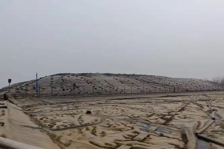
Case Study: The Shenzhen Landfill Failure (2008)
This event is a stark lesson in the consequences of failed leachate management.
- The Buildup: The landfill's leachate collection pipes became clogged, preventing proper drainage. Over several months, the leachate level inside the landfill rose to within just 2 meters of the slope surface.
- The Trigger: A period of heavy rain rapidly added more liquid to the already full "bathtub."
- The Failure: The immense weight and hydrostatic pressure of the high leachate level reduced the friction between the geomembrane liner and the underlying layers to almost zero. This caused a massive section of the slope to fail, resulting in a landslide. The integrity of the entire containment system was compromised in a single event.
The Root Cause: Leachate Collection System (LCS) Clogging
The Shenzhen failure was triggered by high leachate head, but it was caused by a clogged LCS. LCS pipes, typically surrounded by a gravel drainage layer, can become blocked through several mechanisms:
- Sedimentation Clogging: Fine soil particles from overlying layers wash into the drainage gravel and pipes, physically restricting flow.
- Biological Clogging: Microorganisms thrive in the nutrient-rich leachate, forming thick "biofilms" on the surfaces of the gravel and inside pipes, eventually choking off flow.
- Chemical Clogging: If the drainage layer uses carbonate-based stone (like limestone), a chemical reaction with the leachate can cause calcium carbonate (CaCO₃) to precipitate, forming a rock-hard scale that completely blocks pipes.
- Poor Design: Pipe slopes less than 2%, small pipe diameters, and poorly designed junctions create "dead zones" where solids can settle and initiate a blockage.
Geotechnical Instability and Interface Shear Failure
A landfill liner system is a stack of different geosynthetic materials. The friction at the interface between these layers is critical for slope stability.
- Steep Slopes: Slopes designed steeper than 1V:3H (Vertical:Horizontal) are inherently less stable and rely heavily on interface friction to remain in place.
- Low Friction Interfaces: The interface between two smooth geomembranes, or between a smooth geomembrane and a GCL, can have a very low friction angle. When high leachate pressure lubricates this interface, the driving forces of gravity can exceed the frictional resistance, leading to a slippage failure. This can be mitigated by using textured geomembranes, which significantly increase interface friction.
Long-Term Material Degradation
Even a perfectly installed liner will not last forever. Research shows that after approximately 8-10 years of operation, the antioxidants blended into the HDPE resin become depleted. Following this point, the polymer begins to oxidize at an accelerated rate, becoming more brittle and permeable over time. A liner that leaks a few gallons per day when new could leak thousands of gallons per day after 20 years of degradation, even without any obvious tears.
How to Avoid Landfill Liner Failures: A Multi-Layered Strategy
Preventing failure requires a holistic approach that begins at the design stage and continues through the entire operational life of the facility.
1. Robust Design and Engineering
- Conservative Leachate Management: Design the LCS with a massive safety factor. Use pipe slopes of at least 2%, specify chemically stable drainage aggregate (e.g., silica-based gravel), and include a robust geotextile filter layer to prevent soil fines from entering.
- Stable Slope Design: Design slopes to be no steeper than 1V:3H. For very high landfills (>30m), a gentler slope of 1V:3.5H is even safer.
- Anticipate Settlement: Model the expected 20-40% settlement of the waste mass and design the liner and LCS to accommodate this movement without creating excessive stress or low spots where leachate can pool.
- Select the Right Materials: Specify a high-quality HDPE geomembrane with a proven resin, a strong antioxidant package, and a thickness of at least 1.5 mm (2.0 mm is recommended for the base and high-stress areas). Always use textured membranes on slopes.
2. Professional Installation with Rigorous CQA
ضمان جودة البناء (CQA) is a non-negotiable process for verifying that the design is implemented correctly.
- Certified Installers: Only use experienced, certified technicians for geomembrane installation and welding.
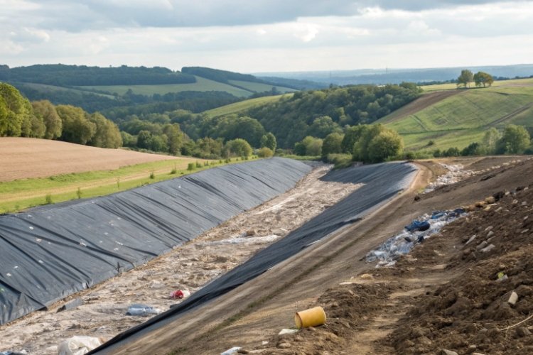
- Meticulous Subgrade Preparation: The surface beneath the liner must be smooth, uniform, and free of any stones or objects that could cause a puncture. A protective, non-woven geotextile should always be placed first.
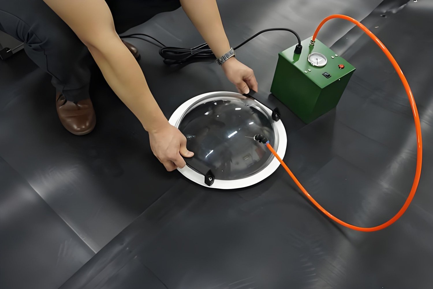
- 100% Seam Testing: Every meter of field seam must be non-destructively tested, typically with a vacuum box or air channel test. Destructive peel and shear tests must also be performed on samples at regular intervals to verify that the weld is as strong as the parent material.
3. Proactive Operational Management
Once the landfill is operational, the focus shifts to monitoring and maintenance.
- Real-Time Leachate Level Monitoring: Install monitoring wells with sensors to provide continuous data on the leachate head. Set alarm levels well below the 30 cm regulatory limit.
- Preventive LCS Maintenance: Implement a schedule for regular high-pressure jet cleaning of the LCS pipes to remove sediment and biofilm before they can form a hard blockage.
- Geotechnical Monitoring: Use inclinometers and survey points to monitor for any signs of slope movement or excessive settlement that could indicate an emerging problem.
4. Emergency Preparedness
Even with the best systems, problems can occur. An emergency action plan is essential.
- Redundant Pumping Capacity: Have backup pumps and power sources ready to be deployed if primary systems fail or if leachate levels begin to rise unexpectedly.
- Emergency Response Plan: The measures used to save the Shenzhen landfill—drilling emergency drainage wells, covering the site to reduce rainwater infiltration, and placing counterweight berms at the toe of the slope—are a model for an effective emergency response.
Regulatory Requirements and Industry Standards
Adherence to established standards is fundamental to liner system success. Key guidelines are provided by organizations like ASTM الدولية and the Geosynthetic Research Institute (GRI). These standards define everything from material properties (e.g., GRI-GM13 for HDPE geomembranes) to proper welding and testing procedures. Compliance is not just a best practice; it is essential for meeting environmental regulations and ensuring long-term liability protection.
خاتمة
Landfill liner failures are complex events, but they are not random. The vast majority are preventable. They are less often the result of a single faulty weld or puncture and more frequently the outcome of a systemic failure to manage leachate. By embracing a multi-layered prevention strategy—starting with a conservative design focused on robust leachate management, enforced by rigorous CQA during construction, and sustained by proactive monitoring and maintenance during operation—we can ensure that engineered containment systems perform their critical function of protecting our environment for decades to come.