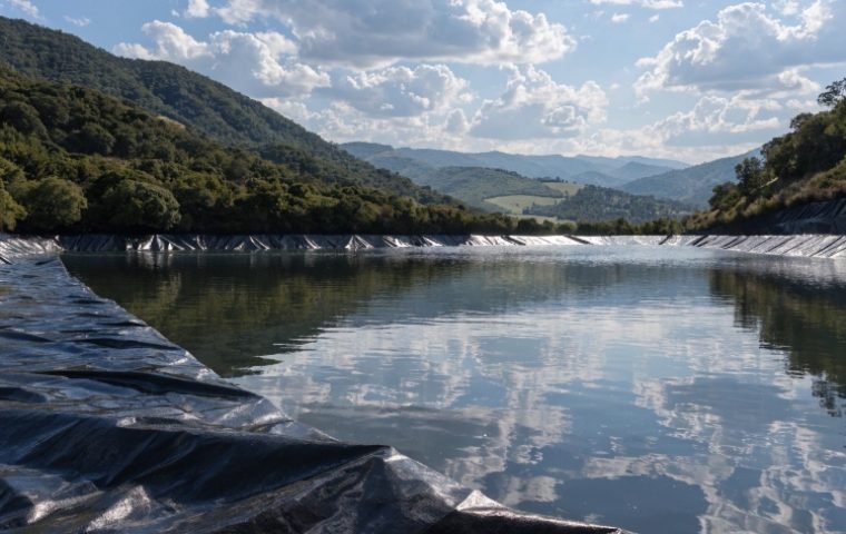
In environmental engineering, the need for reliable subsurface containment barriers is constantly growing. For landfill expansions, contaminated site remediation, and groundwater protection, traditional cutoff walls made from compacted clay or cement-bentonite have often been the standard. However, these methods can be slow, expensive, and achieving a uniform, low-permeability barrier under field conditions is notoriously difficult.
This is where modern geosynthetics provide a superior alternative. Vertical Geosynthetic Clay Liner (GCL) composite cutoff walls combine the factory-controlled quality of a GCL with a low-permeability backfill to create a highly effective, continuous underground barrier. This system is not only more reliable but is also significantly faster and more cost-effective to install, making it a preferred solution for many advanced containment projects.
This guide provides a detailed breakdown of the construction methods, key technical considerations, and quality control measures essential for the successful installation of a vertical GCL composite cutoff wall. We will walk through the process from site preparation to final quality checks, sharing insights from our field experience to help you execute your project correctly.
Structure and Working Principle of a Vertical GCL Wall
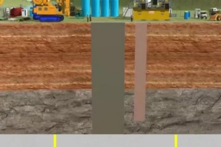
Before diving into construction, it's important to understand the components of the system and how they work together. A vertical GCL composite wall is fundamentally a dual-barrier system composed of three main parts:
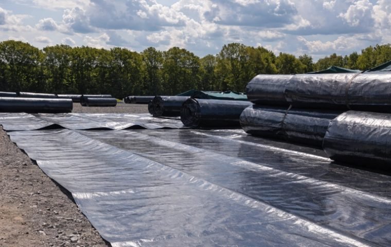
- The Geosynthetic Clay Liner (GCL): This is the primary waterproofing element. It consists of a layer of high-swelling sodium bentonite clay factory-sealed between two geotextiles.
- The Backfill: This is a low-permeability mixture, typically composed of excavated soil blended with bentonite (a Soil-Bentonite or "SB" mix), that fills the majority of the trench.
- The Support Structure: During excavation, the trench is not left open. It's supported by a bentonite slurry, which prevents the trench walls from collapsing until the backfill is placed.
The waterproofing mechanism is twofold. The GCL provides an extremely low-permeability membrane (often ≤5×10⁻¹¹ m/s) that swells to self-heal minor punctures. The SB backfill provides a secondary, thicker barrier with a target permeability of ≤1×10⁻⁹ m/s (≤1×10⁻⁷ cm/s). Together, they form a robust, continuous, and flexible underground barrier. The system's performance depends entirely on the GCL's continuity, its intimate contact with the surrounding soil, and its ability to fully hydrate under confinement.
Construction Method for Vertical GCL Composite Walls
This is a systematic, multi-stage process where each step builds upon the last. Precision and control at every stage are critical.
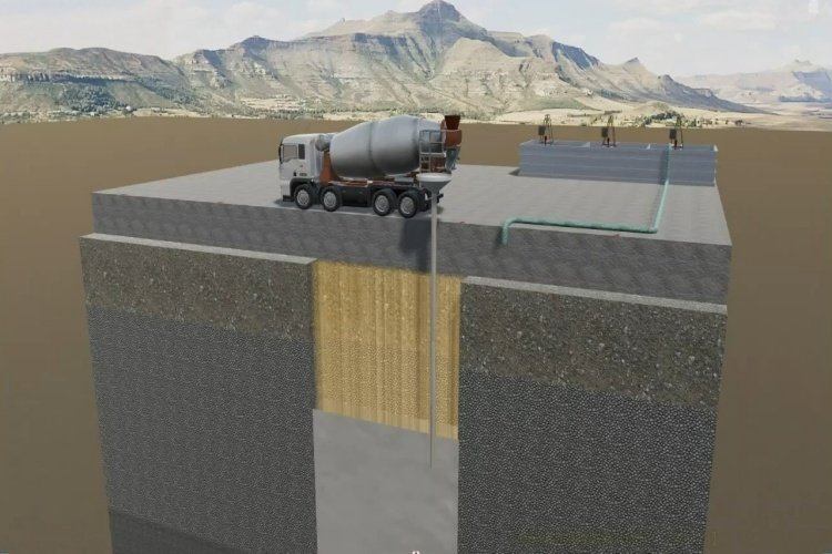
1. Site Preparation and Trenching
The process begins with standard surveying and site clearing. The centerline of the wall is staked out, and a work platform is prepared for the heavy equipment. The core of this stage is the trench excavation itself.
- Excavation: The trench is dug using a long-reach excavator for moderate depths or a mechanical clamshell for deep walls (depths can exceed 50 meters). The trench width is typically between 0.6 to 1.2 meters.
- Slurry Support: As the trench is excavated, it is immediately filled with a bentonite slurry. This slurry serves a crucial purpose: its hydrostatic pressure counteracts the pressure from groundwater and soil, preventing the trench from collapsing. It is not just "muddy water"; it is an engineered fluid.
- Slurry Quality: The slurry properties must be strictly controlled. Key parameters include:
- Viscosity: A Marsh funnel viscosity of 35-50 seconds for fresh slurry ensures it can suspend soil particles without being too thick to pump.
- Density: A unit weight of 13-15 kN/m³ provides the necessary hydrostatic force for trench stability.
- Sand Content: Must be kept below 4% to prevent sand from settling out and creating permeable zones.
- Slurry Head: The slurry level in the trench must be kept at least 1 meter (3.3 feet) above the surrounding groundwater table at all times to ensure positive pressure against the trench walls.
2. Vertical Placement of the GCL
Once a section of the trench is excavated to the target depth and the slurry is stabilized, the GCL panel is installed.
- Deployment: The GCL is delivered in large rolls. It is attached to a weighted steel frame or spreader bar and carefully lowered into the slurry-filled trench by a crane.
- Alineación: The GCL must be lowered vertically and kept in contact with one wall of the trench. The goal is to ensure the panel is smooth, continuous, and free of folds or wrinkles. Depending on the design, GCLs can be placed on one side or both sides of the trench for enhanced security.
- Continuity: Meticulous records must be kept to track the position of each panel and ensure there are no gaps between them. The top of the GCL is secured at the surface until backfilling is complete.
3. Panel Overlaps and Sealing
The connection between two adjacent GCL panels is the most critical point for potential leakage.
- Ancho de superposición: Una superposición mínima de 150 mm to 300 mm (6 to 12 inches) must be achieved between adjacent vertical panels.
- Seal Enhancement: To ensure a waterproof seal, a bead of pure bentonite paste or granular bentonite is applied along the edge of the first panel antes the second panel is lowered and overlapped. This creates a bentonite-rich zone at the seam, promoting a monolithic seal upon hydration.
- Verification: While direct visual inspection is impossible inside the slurry, proper placement is confirmed through careful measurements, crane operator control, and sometimes underwater cameras in critical applications.
4. Backfill Mixing and Placement
The backfill is typically a Soil-Bentonite (SB) mixture. It is designed not only to be a low-permeability barrier but also to be flowable enough to displace the slurry in the trench.
- Mix Design: The mix consists of excavated soil, bentonite (typically 3-5% by dry weight), and water. The goal is to create a homogenous mixture with a "wet concrete" consistency. For higher strength requirements, a Soil-Cement-Bentonite (SCB) mix can be used.
- Slump Control: The consistency is measured by a slump test. This is the most critical parameter for backfill placement.
- Ideal Slump: 75-150 mm (3-6 inches). This makes the mix flowable enough to displace the lighter slurry but cohesive enough to prevent its components from separating.
- Too Low (<50 mm): The mix is too stiff and will not flow correctly, potentially trapping pockets of slurry (known as "slurry inclusions"), which create weak, permeable zones.
- Too High (>150 mm): The mix is too wet. Sand and gravel can segregate and settle at the bottom of the trench, forming a highly permeable "sand lens."
- Colocación: The backfill is placed into the trench using a tremie pipe or by carefully discharging it from an excavator bucket at one end of the trench. The heavier backfill flows down and along the trench bottom, displacing the lighter slurry, which is pumped out from the far end of the trench and recycled.
Key Considerations During Construction
Success lies in managing details and anticipating problems.
- Prevent Premature GCL Hydration: The GCL rolls must be kept dry on site before installation. While the GCL will be submerged in the slurry during placement, prolonged exposure of the overlaps to rain before installation can compromise the bentonite.
- Avoid Mechanical Damage: Handle the GCL panels with care. Do not drag them. Ensure the deployment frame has no sharp edges. Any damage to the geotextile can lead to bentonite loss.
- Ensure Continuity at All Costs: The entire barrier is only as good as its weakest point. Double-check overlap procedures, monitor panel alignment, and ensure no gaps are left between panels.
- Manage Groundwater and Weather: In areas with a high water table, the dewatering and slurry head management system must be robust. Avoid excavation during heavy rain, as it can dilute the slurry and increase the risk of trench collapse.
Quality Control and Testing Methods
A rigorous quality control (QC) program is not optional; it is essential.
- Pre-Construction: Laboratory tests should be performed on the proposed backfill mix design using site-specific soil and water to confirm it can achieve the required permeability (≤1×10⁻⁹ m/s).
- During Construction - Slurry: The viscosity, density, and sand content of the bentonite slurry must be tested multiple times per shift.
- During Construction - Backfill: The slump of every batch of backfill mix must be tested before it is placed in the trench. Samples should also be taken regularly (e.g., every 500 cubic meters) to cast cylinders for laboratory permeability and strength testing.
- Post-Construction: After the wall has cured, core samples can be taken from the finished wall to verify its in-situ properties and confirm that the permeability meets the design specification.
Common Problems and How to Avoid Them
| Problem | Cause | Prevention / Solution |
|---|---|---|
| Trench Collapse | Insufficient slurry head; low slurry viscosity or density. | Maintain slurry level >1m above groundwater; rigorous and frequent slurry testing. |
| Slurry Inclusions | Backfill slump is too low; improper placement method. | Strict slump control (75-150 mm); continuous placement from one end. |
| Sand Lenses | Backfill slump is too high, causing material segregation. | Strict slump control; ensure a well-graded backfill mix, not just sand. |
| Seam Failure | Insufficient overlap; GCL panels misaligned. | Use a weighted deployment frame; careful crane operation; robust overlap procedure with ancillary bentonite. |
To further enhance performance, especially in aggressive chemical environments, consider using polymer-modified GCLs. Integrating a long-term monitoring system with piezometers can also provide valuable data on the wall's ongoing performance.
Conclusión
The construction of a vertical GCL composite cutoff wall is a sophisticated geotechnical process that offers unparalleled performance when executed correctly. While the technology is advanced, the formula for success is based on fundamental principles: meticulous preparation, strict process control, and continuous quality assurance. By managing the trenching slurry, ensuring proper GCL placement and sealing, and rigorously controlling the backfill mix and placement, you can build a durable and effective underground barrier that provides reliable environmental protection for decades to come.