Prilikom projektiranja sustava za zadržavanje odlagališta, lako se usredotočiti isključivo na specifikacije same geomembrane - njenu debljinu, materijal i čvrstoću šava. Međutim, dugoročna izvedba te obloge duboko je pod utjecajem okoline u kojoj je postavljena. Tri kritična, a često zanemarena čimbenika – geometrija mjesta i temelj – jednako su važni kao i materijal koji odaberete. To su nagib odlagališta, veličina ćelije i kvaliteta podloge.
Kao a dobavljač geosintetike, iz prve smo ruke vidjeli kako sjajan sustav obloga može biti ugrožen lošim geometrijskim dizajnom ili nestabilnim temeljima. Obloga nije izolirani element; dio je složenog interaktivnog sustava. Razumijevanje ovog odnosa ključ je za dizajniranje sustava za zadržavanje koji nisu usklađeni samo prvog dana, već su sigurni i učinkoviti desetljećima. Ovaj vodič istražuje kritičan utjecaj nagiba, veličine ćelije i temeljnog sloja na performanse košuljice, pružajući inženjerska načela koja su vam potrebna da biste to učinili kako treba.
Započnimo ispitivanjem kako kut tla ispod obloge diktira njenu stabilnost i učinkovitost.
1. Kritični utjecaj nagiba odlagališta na performanse košuljice
Kut nagiba je čin ravnoteže između učinkovite drenaže i mehaničke stabilnosti. Različiti dijelovi odlagališta zahtijevaju različite nagibe, a svaki ima posebnu funkciju.
| Vrsta nagiba | Tipični raspon | Funkcija | Ključni zahtjev |
|---|---|---|---|
| Osnovni nagib | 2% – 4% | Odvodnja procjednih voda | ≥1% uzdužno, ≥3% poprečno na cijevi |
| Bočni nagib | 1V:3H – 1V:2,5H | Stabilnost otpadne mase | Faktor sigurnosti (FOS) ≥ 1,5 |
| Završna naslovnica | ≤ 1V:3H | Spriječite eroziju | Podržavajte vegetaciju, kontrolirajte otjecanje |
Napomena: 1V:3H znači 1 metar okomito za svaka 3 metra vodoravno.
Učinkovitost odvodnje padina i procjednih voda
Primarna svrha osnovnog nagiba je korištenje sile teže za usmjeravanje procjedne vode prema sabirnim cijevima. Učinkovitost ovog procesa regulirana je Darcyjevim zakonom, koji nam govori da je brzina protoka izravno proporcionalna hidrauličkom gradijentu—u ovom slučaju, nagibu košuljice.
Strmiji nagib znači bržu drenažu i manju visinu procjedne vode (dubina tekućine koja se nalazi na liniji). Ovo je ključno za smanjenje rizika od curenja.
- Strmi nagib (npr. 4%): Procjedne vode brzo otječu, držeći visinu ispod 100 mm.
- Plitki nagib (npr. 2%): Drenaža je sporija, a visina može porasti do 300 mm, što je često najveća dopuštena granica.
- Ravna padina (<1%): Dolazi do značajnog skupljanja, koje potencijalno prelazi granicu od 300 mm i dramatično povećava pritisak na košuljicu i njezine spojeve.
Međunarodni standardi, uključujući one iz US EPA, obično propisuju minimalni nagib od 1% duž cijevi za prikupljanje procjedne vode i nagib od 2%–4% poprečno (okomito) na njih kako bi se osigurala kontrola glave procjedne vode.
Stabilnost nagiba i linije
Iako je strma padina dobra za odvodnju, ona predstavlja veliki rizik za stabilnost bočnih padina. Težina sustava obloga, pokrovnog tla i samog otpada stvara gravitacijske sile (pogonske sile) koje žele povući cijelu masu nizbrdo. Tome se suprotstavljaju sile trenja (sile otpora) na različitim sučeljima unutar sustava košuljice.
Inženjeri to analiziraju pomoću a Metoda granične ravnoteže za izračun faktora sigurnosti (FOS):
FOS = Resisting Forces / Driving Forces
FOS od 1,0 znači da je sustav na rubu kvara. Siguran dizajn zahtijeva FOS ≥ 1,5. Sile otpora uvelike ovise o kutovima trenja između slojeva (npr. geomembrane prema GCL-u, GCL-u podlozi). Strmiji kut nagiba dramatično povećava pogonske sile, izlažući sustav riziku od proklizavanja. Zbog toga se bočne padine rijetko projektiraju strmije od 1V:2,5H (približno 22°) bez opsežne geotehničke analize i potencijalnog ojačanja.
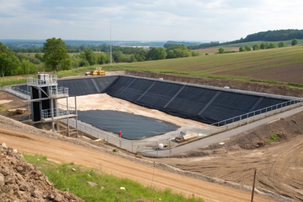
2. Kako veličina ćelije utječe na opterećenje obloge i učinkovitost sustava
A landfill is typically constructed in discrete phases, or "cells." Ćelija je potpuno zatvoreno područje s vlastitom oblogom i sustav za sakupljanje procjednih voda. Veličina ovih ćelija ima značajan utjecaj na konstrukciju, rad i performanse.
| Veličina ćelije | Tipični volumen (m³) | Uobičajena primjena |
|---|---|---|
| Mali | 50.000 – 200.000 | Fazna izgradnja; dobro za izolaciju curenja |
| srednje | 200.000 – 1.000.000 | Najčešća veličina, balansiranje učinkovitosti i upravljanja |
| velika | > 1.000.000 | Objekti velikih razmjera; složenije upravljanje procjednim vodama |
Veličina ćelije i sakupljanje procjedne vode
Veličina i oblik ćelije izravno diktiraju raspored mreže cijevi za prikupljanje procjednih voda. Propisi često zahtijevaju da razmak između cijevi ne bude veći od 25-50 metara kako bi visina procjedne vode bila ispod granice od 300 mm.
To znači da veća ćelija ne treba samo duže cijevi; to treba više njih, što dovodi do složenijeg sustava. Širi pod ćelije povećava maksimalnu udaljenost putovanja za procjednu vodu, što može dovesti do viših razina visine između odvodnih cijevi.
Veličina ćelije i ugradnja obloge
- Velike ćelije: S jedne strane, velika, otvorena područja omogućuju učinkovitije postavljanje geosintetičkih ploča, s manje zaustavljanja i pokretanja. S druge strane, oni su osjetljiviji na izazove toplinskog širenja i skupljanja. Za vrućeg, sunčanog dana, velika izložena ploča geomembrane može razviti značajne nabore. Ako se te bore ne kontroliraju i prekriju, mogu postati točke visokog stresa i potencijalnog kvara.
- Male ćelije: Manje ćelije pojednostavljuju upravljanje borama, ali povećavaju ukupnu gustoću šavova u odnosu na područje. To znači više zavarivanja, više QA/QC testiranja i veći broj potencijalnih slabih točaka ako nije ispravno instaliran.
Iz tih razloga, većina modernih odlagališta projektirana je primjenom faznog pristupa s više ćelija. To osigurava radnu fleksibilnost, omogućuje brzo izoliranje curenja i čini upravljanje procjednom vodom i plinom učinkovitijim.
3. Temeljna uloga kvalitete podloge za cjelovitost košuljice
Podloga — pripremljena temeljna zemlja na kojoj je izgrađen sustav obloga — najpodcijenjenija je komponenta sustava zadržavanja. Loša podloga može dovesti do kvara obloge bez obzira na kvalitetu geosintetike.
Zbijenost podloge i nosivost
Podloga mora osigurati stabilnu, nepopustljivu platformu. Nedovoljno zbijanje primarni je uzrok budućih problema.
| Lokacija podloge | Minimalno zbijanje (Proctor) | Svrha |
|---|---|---|
| Baza | ≥ 95% MDD | Izdržati najveći pritisak mase otpada |
| Bočne padine | ≥ 90% MDD | Spriječite ljuštenje i osigurajte stabilnost |
Ako je podloga slabo zbijena, pod ogromnom težinom otpada (koja može premašiti 600 kPa) neravnomjerno će se slijegati. Ovaj diferencijalno poravnanje rasteže geomembranu preko udubljenih područja, stvarajući visoko vlačno naprezanje koje može dovesti do pucanja i kvara.
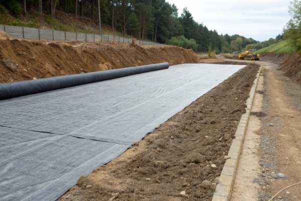
Priprema podloge
Obloga mora imati blizak kontakt s podlogom. Površina mora biti:
- Glatko i bez krhotina: Potrebno je ukloniti sve kamenje veće od 12 mm, korijenje i oštre predmete.
- Čak: The surface should be graded to a tolerance of about +/- 25 mm to prevent the liner from "bridging" preko praznina.
- Dobro zbijeno: Čvrsta površina sprječava građevinsku opremu da stvori duboke brazde koje mogu opteretiti košuljicu.
Geotekstilni jastučić postavljen izravno na podlogu često je neophodan za zaštitu geomembrane od bilo kakvih preostalih nesavršenosti.
Međusklopna čvrstoća na smicanje
The friction between the liner system and the subgrade is a key component of slope stability. This "interface shear strength" mjeri se u laboratoriju i kritičan je za izračun faktora sigurnosti. Glatka, vlažna glinena podloga imat će puno niži kut trenja međusklopa s geomembranom u usporedbi s granuliranim, zbijenim tlom, što je čini manje prikladnom za strme padine.
4. Sinergijski učinak: koordiniranje nagiba, veličine ćelije i podloge
Ova tri faktora ne djeluju izolirano. Njihov zajednički učinak određuje ukupnu učinkovitost i sigurnost sustava.
| Scenarij | Nagib | Glava procjedne vode | Kvaliteta podloge | Rezultat (faktor sigurnosti) |
|---|---|---|---|---|
| Optimalno | Strmo (4%) | Nisko (<100 mm) | Izvrsno (≥95% zbijenosti) | FOS > 2.0 (vrlo sigurno) |
| Marginalni | Srednje (2%) | Visoko (300 mm) | Dobro (90% zbijenosti) | FOS ≈ 1,5 (pozorno promatrajte) |
| opasno | Plitko (1%) | Vrlo visoko (>300 mm) | Jadno (<90% zbijanja) | FOS < 1.5 (Visoki rizik od kvara) |
Dobar dizajn je iterativni proces:
- Predlaže se početni nagib i raspored ćelija.
- Sustav za upravljanje procjednim vodama dizajniran je za održavanje pada ispod 300 mm.
- Zahtjevi za podlogu su navedeni.
- Provodi se analiza stabilnosti (FOS).
- Ako je FOS prenizak, projektant mora napraviti promjenu: smanjiti kut nagiba, poboljšati podlogu ili dodati armaturu. Ovaj se postupak ponavlja dok se ne zadovolje svi kriteriji sigurnosti i učinkovitosti.
Zaključak
Uspješan sustav obloga odlagališta izgrađen je na temeljima dobrog geotehničkog i geometrijskog dizajna. Pažljivim razmatranjem međudjelovanja između kuta nagiba, konfiguracije ćelija i kvalitete podloge, idete dalje od jednostavnog odabira materijala. Vi projektirate potpuni, integrirani sustav dizajniran za dugoročnu stabilnost i zaštitu okoliša. Obraćanje velike pozornosti na ove temeljne elemente od samog početka je najučinkovitiji način da se osigura cjelovitost i dugovječnost cijelog odlagališta.