A perfectly specified and expertly welded geomembrane can still fail if its edges are not properly secured. An improperly designed anchor trench can lead to liner pullout, wind uplift, and catastrophic system failure, turning a significant investment into a costly liability. This guide provides a detailed, practical framework for designing and constructing anchor trenches that guarantee the long-term integrity and performance of your entire geosynthetic lining system.
This guide covers the essential engineering principles behind geomembrane anchor trenches. We will explore the critical design parameters, construction best practices, and quality assurance procedures needed to create a secure anchor that withstands environmental stresses and ensures your project's success from day one.

An anchor trench is far more than just a place to bury the edge of a liner; it is a critical structural component of the containment system. Understanding its function is the first step toward a successful installation.
1. Functional Role and Engineering Requirements of Anchor Trenches
The primary function of an anchor trench is to provide a fixed point of termination for the geomembrane, securely locking it into the surrounding subgrade. This mechanical connection is vital for resisting a variety of forces that would otherwise compromise the liner system.
As suppliers, we often see projects where the focus is almost entirely on the liner material and the seams, while the anchor trench is treated as an afterthought. This is a mistake. A properly engineered trench must perform several critical functions simultaneously:
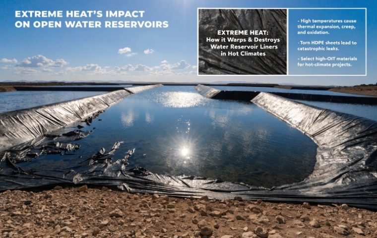
- Resist Wind Uplift: On exposed liners, wind can get underneath the geomembrane and create a powerful upward force. The anchor trench provides the necessary dead weight and frictional resistance to hold the edge down.
- Counteract Sliding and Pullout Forces: On sloped applications, the weight of cover soils, snow, or the liner itself creates a constant gravitational pull. The trench provides the pullout resistance needed to prevent the liner from sliding down the slope.
- Accommodate Thermal Expansion and Contraction: Geomembranes expand and contract with temperature changes. A correctly designed trench allows for some slack, preventing tensile stresses from concentrating at the anchor point and potentially tearing the material.
- Provide a Stable Termination Point: The trench offers a clean, protected, and stable location to end the liner, preventing erosion from undercutting the edge and ensuring a durable installation.
2. Types of Anchor Trenches: Top-of-Slope, Intermediate, and Bottom Anchors
While the concept is the same, anchor trenches can be located at different points in a lining system depending on the project's geometry and engineering needs. The vast majority of applications use a top-of-slope anchor, but it's important to recognize the others.
Top-of-Slope Anchor Trench
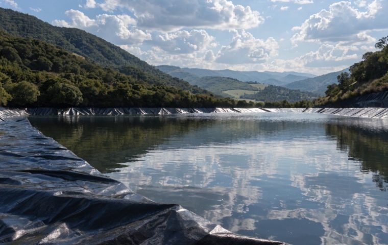
This is the most common type, excavated along the perimeter crest or berm of a containment facility like a pond, landfill, or reservoir. It secures the upper edge of the geomembrane panels after they are draped over the slopes. It's designed to handle the primary tensile and wind uplift forces acting on the system.
Intermediate Anchor Trench
For very long or steep slopes, an intermediate anchor trench may be required partway down the slope. Its purpose is to break up the total length of the liner panel, reducing the cumulative gravitational load on the upper anchor trench. This helps manage tensile stresses within the geomembrane and improves overall slope stability.
Bottom Anchor (Toe) Trench
In some designs, an anchor trench is also constructed at the toe (bottom) of the slope where it meets the floor of the containment area. This provides an additional securing point, preventing liner movement from the bottom up and helping to manage forces in very deep or large facilities.
3. Design Parameters: Depth, Width, Angle, and Embedment Considerations
The effectiveness of an anchor trench is determined by its physical dimensions and geometry. These are not arbitrary figures; they are calculated based on site-specific conditions. However, there are common industry standards that serve as a starting point.
A standard anchor trench is typically 0.5 to 1.0 meters (1.5 to 3 feet) deep da 0.5 to 1.0 meters (1.5 to 3 feet) wide. These dimensions provide sufficient embedment and backfill volume to generate the required resistive forces for most applications.
Key design considerations we always emphasize include:
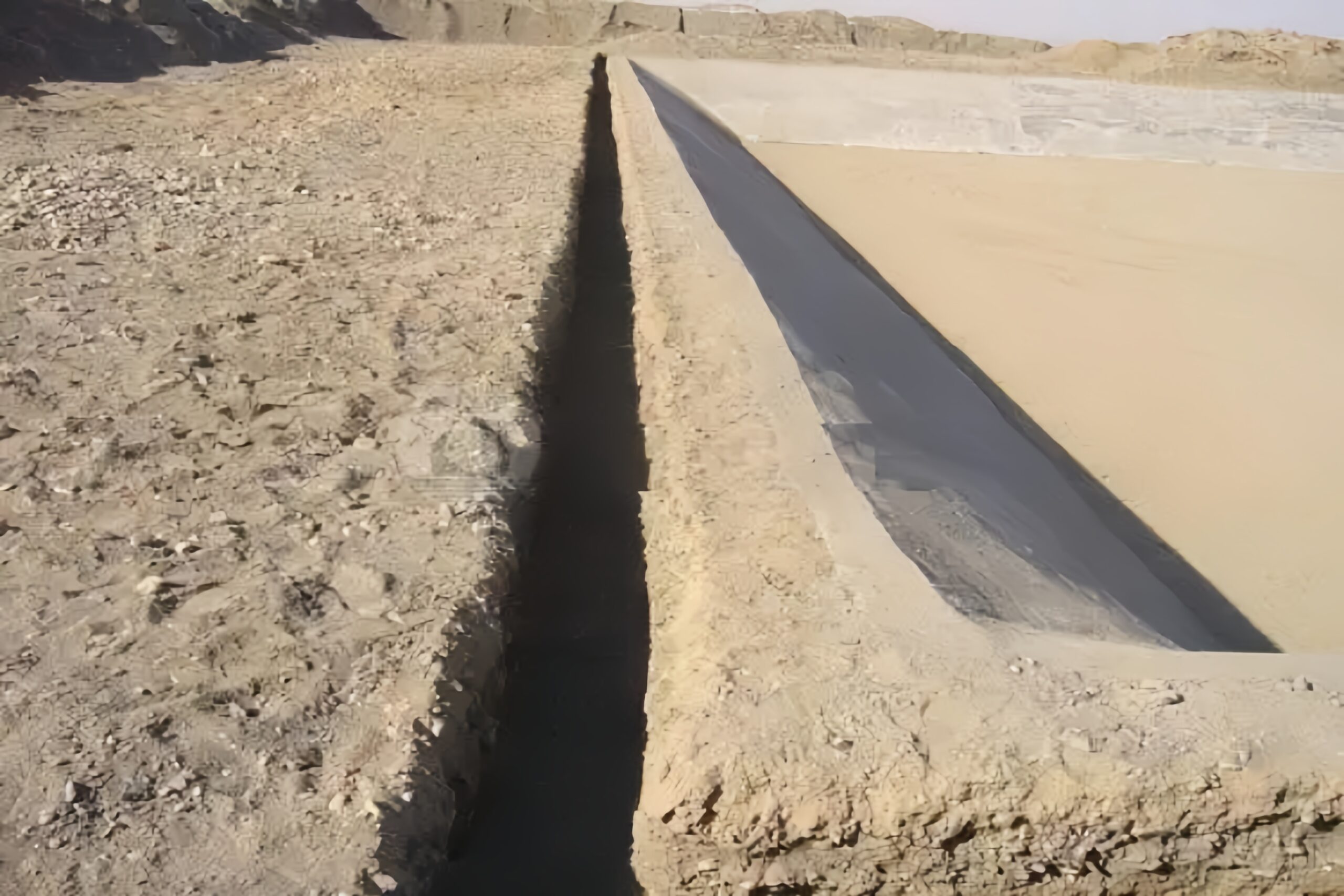
- Setback Distance: The trench should be excavated approximately 0.6 meters (2 feet) back from the crest of the slope. This setback prevents the trench from being located in soil that could be weakened by surface erosion and ensures a stable mass of earth between the trench and the slope.
- Rounded Corners: The corner where the geomembrane exits the slope and enters the trench must be rounded and smooth. A sharp, 90-degree angle creates a point of high stress concentration that can lead to fatigue and failure of the liner over time.
- Smooth Surfaces: The walls and floor of the excavated trench must be smooth, firm, and free of any sharp rocks, roots, or debris that could puncture the geomembrane.
4. Design Calculations: Uplift Resistance, Pullout Forces, and Safety Factors
While we don't perform the final engineering calculations, we work with contractors who do, and it's essential to understand the principles involved. The design of an anchor trench is a balance of forces.
- Acting Forces: These are the loads trying to pull the geomembrane out of the trench. They include wind uplift, the downslope weight of the liner and any cover soil, and tensile forces from thermal contraction.
- Resistive Forces: These are the forces holding the geomemembrane in the trench. They are primarily generated by the weight of the compacted backfill material on top of the liner and the frictional resistance between the geomembrane and the backfill soil.
The design engineer calculates these forces and ensures that the resistive forces are significantly greater than the acting forces. This ratio is known as the Factor of Safety (FS). A typical design might require a Factor of Safety of 1.5 or higher, meaning the trench is designed to resist at least 50% more force than it is expected to encounter during its service life. These calculations determine the final required depth and width of the trench.
5. Material Selection and Soil Compatibility Guidelines
The type of soil at the project site directly influences the optimal shape of the anchor trench. A one-size-fits-all approach can lead to instability or construction difficulties. The geometry should be adapted to ensure the trench walls do not collapse before or during liner placement.
Based on our experience with various geological conditions globally, we recommend the following trench profiles:
| Soil Type | Recommended Trench Shape | Dalilin dalili |
|---|---|---|
| Clay Soils | V-Shaped Trench | Clay has high cohesion, allowing it to hold a steep angle without collapsing. This shape minimizes the amount of excavation required. |
| Silty and Sandy Soils | Trapezoidal Trench | These soils are less cohesive and prone to sloughing. A sloped, trapezoidal shape provides stable walls and is easy to work in. |
| Rocky Terrain | Square or Rectangular Trench | In rocky ground or very competent soil, vertical walls are often stable. This shape is straightforward to excavate with a standard backhoe bucket. |
Regardless of the shape, the principle remains the same: ensure the trench is stable enough for safe entry (if required) and for the proper placement and backfilling of the geomembrane.
6. Construction Methods and Sequence of Works
Proper construction sequencing is crucial for the success of an anchor trench. Rushing or performing steps out of order can compromise both the subgrade and the geomembrane.
Here is the step-by-step process we advise our clients to follow:
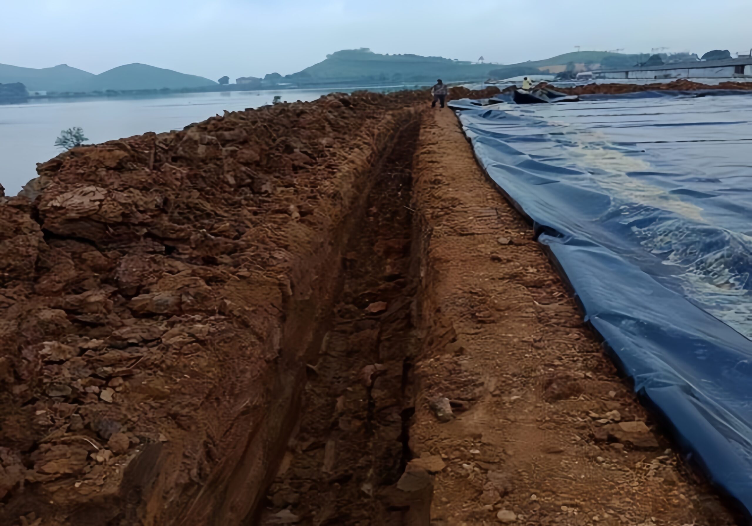
- Excavation: Excavate the trench to the lines and grades specified in the engineering drawings. To prevent the subgrade soil from drying out and losing strength (desiccation), only excavate a length of trench that can be lined and backfilled within a short period, often one day's work.
- Trench Preparation: Inspect the excavated trench. Remove any loose rocks, debris, or sharp objects. Round the edges and corners as required. The surface must be smooth enough not to damage the liner.
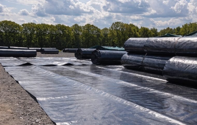
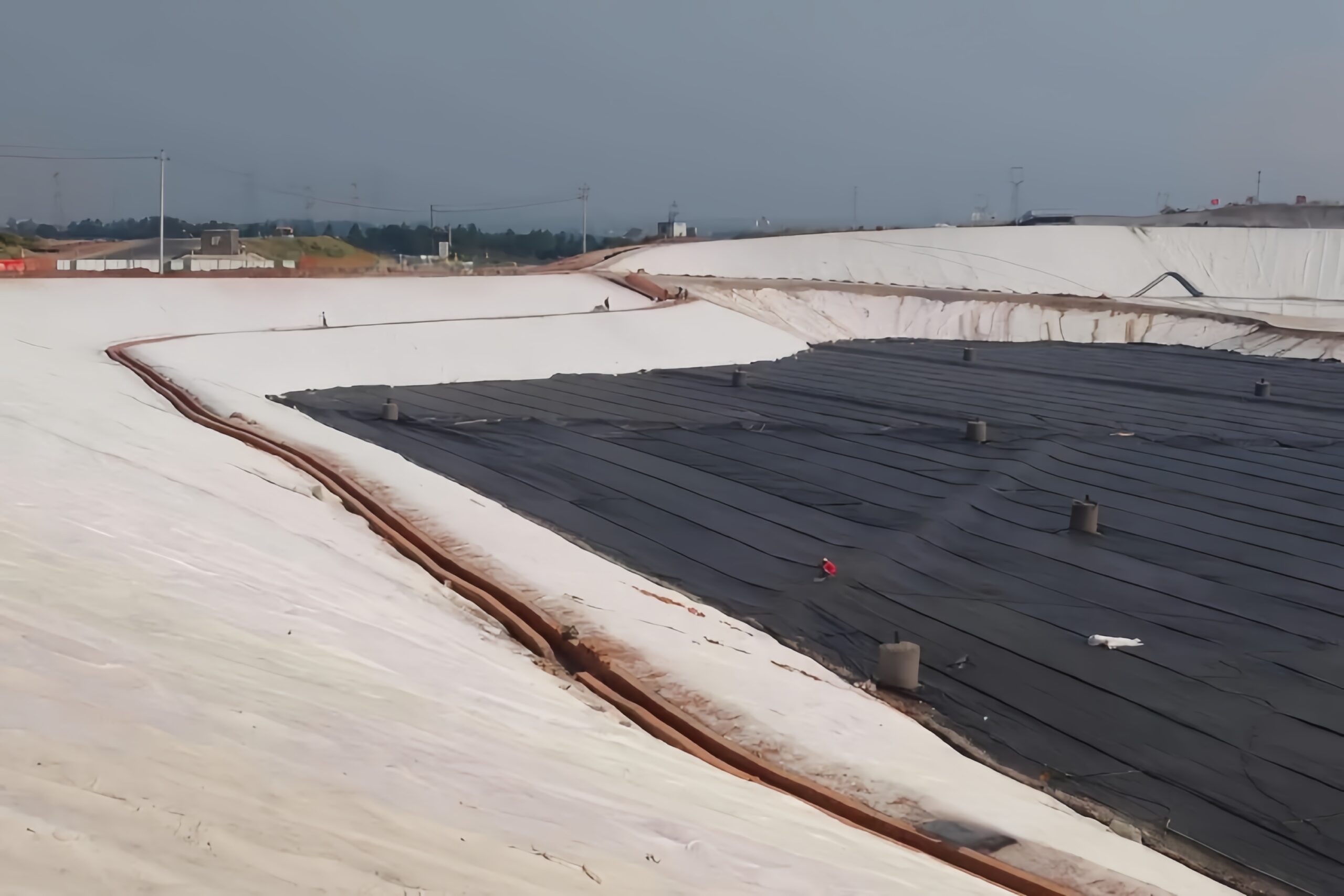
- Liner Placement: Carefully drape the geomembrane panel over the slope and into the trench. Ensure there is enough slack so the liner rests flat against the bottom and walls of the trench without any tension.
- Temporary Ballasting: Place sandbags or other temporary weights on the liner inside the trench to hold it in position and prevent it from being moved by wind.
- Backfilling and Compaction: Once the liner panel is fully welded and inspected, the trench can be backfilled. Place soil back into the trench in lifts (layers), compacting each lift according to project specifications. Care must be taken not to damage the geomembrane with construction equipment.
7. Quality Assurance: Testing, Inspection, and Verification Procedures
Continuous quality assurance (QA) is not optional; it's essential. Every step of the anchor trench construction should be verified to prevent hidden defects that could lead to future failure.
A robust QA program should include the following checks:
- Pre-Placement Inspection:
- Verify trench dimensions (depth, width, setback) against the design drawings.
- Inspect the trench for smoothness, ensuring no rocks or debris are present.
- Confirm that corners are properly rounded.
- During Placement Inspection:
- Check that the geomembrane is placed without tension or "bridging" across corners.
- Ensure temporary sandbags are sufficient to hold the liner securely.
- Post-Backfill Inspection:
- Monitor the backfilling process to ensure the specified soil is used and compaction efforts meet the required density.
- Visually inspect the area after backfilling to ensure there is no remaining damage to the exposed geomembrane near the trench.
8. Alternative Anchoring Methods and Application Scenarios
While the standard backfilled trench is most common, some situations require alternative anchoring methods, especially when terminating the geomembrane against a rigid structure like concrete.
Scenario 1: Standard Soil Berm (Top-of-Slope)
This is the classic application described throughout this guide. A trapezoidal or V-shaped trench is excavated into an earthen berm, and the liner is secured with compacted soil backfill. This is the preferred method for ponds, landfills, and reservoirs.
Scenario 2: Termination Against a Concrete Wall
When the liner must terminate against a vertical concrete wall or structure, a trench is not feasible. In this case, a common method is batten strip anchoring.
- The geomembrane is pressed against the concrete wall.
- A flat bar of stainless steel or aluminum (the batten) is placed over the liner.
- Mechanical anchors (like expansion bolts or shot nails) are fastened through the batten and liner into the concrete at close intervals (typically less than 0.4m or 16 inches).
- A bead of sealant is often applied along the top edge of the batten to create a watertight seal.
Scenario 3: Embedded Anchors
For new concrete structures, an even more robust connection can be created using embedded anchor profiles. T-lock or E-lock strips—extruded plastic profiles with extensions—are cast directly into the concrete when it is poured. Later, the geomembrane can be welded directly to the exposed plastic profile, creating a continuous, high-strength, and leak-proof connection.
9. Long-Term Performance, Maintenance, and Failure Prevention
A well-built anchor trench should require minimal maintenance, but it should not be forgotten. The biggest long-term risk is erosion of the soil covering and surrounding the trench.
Regular inspections, especially after major storm events, should be conducted to check for:
- Surface Erosion: Look for any signs of rills or gullies forming on or near the trench area. If the backfill erodes, the anchoring strength will be reduced.
- Settlement: Any significant sinking or depression over the trench could indicate poor compaction of the backfill, which may need to be remediated.
- Animal Burrows: Burrowing animals can compromise the integrity of the soil berm and backfill.
By catching these issues early and restoring cover soil as needed, you can ensure the anchor trench continues to perform its critical function for the entire design life of the project.
Ƙarshe
The anchor trench is the foundation of a secure geomembrane lining system. Its design and construction demand the same level of engineering rigor and quality control as the liner material and welding. By carefully considering the design parameters, soil conditions, construction sequence, and alternative methods, you can ensure your project's edges are secured for decades of reliable performance, preventing costly failures and protecting your investment.